3

I'm using an Arduino Due that talks via SPI to an LCD (800x480) with the RA8875 controller chip. The most recent datasheet I could find is: RA8875 datasheet. Everything works as expected when using the Adafruit library. But, for my project, I want to maximize the communication speed between the LCD and the Arduino DUE.

Page 60 of the datasheet tells me that the maximum SPI speed to perform a SPIread is

system clock / 6.

Page 39 gives the formula for the system clock:

SYS_CLK = FIN * ( PLLDIVN [4:0] +1 ) / (( PLLDIVM+1 ) * ( 2^PLLDIVK [2:0] ))

There are some constraints:

  1. From page 39:
    FPLL = FIN * ( PLLDIVN [4:0] +1 ) must be equal to or greater than 110 MHz

  2. From page 91:
    For an LCD of dim 800x480 2 layers 8bit color depth 60Hz framerate the pixel clock should be between 30 and 33MHz. (Registers are set to have 2 layers and 8 bit color depth).

A crystal of 20Mhz is soldered on the LCD ( FIN = 20 Mhz)

I have set the registers as follows:

Register Value
PLLC1[88h] 24
PLLC1[89h] 1
PCSR[04h] 3

So, I expect:

  • SYS_CLK = 20 Mhz * ( 24 +1 ) / (( 0+1 ) * ( 2^1 )) = 250 Mhz
  • Pixel clock = SYS_CLK / ( 2^3 ) = 31.25 Mhz
  • Max. spi speed = 250 Mhz / 6 = 41.66 Mhz.

I think to obey every given constraint. But when I use an spi-speed of 30 Mhz, which is below 41.66 Mhz, I get a black screen.

I've put the Arduino sketch and the modified Adafruit library (Sven_RA8875) on google drive: Arduino sketch + modified library.

The same data but on a pastebin:

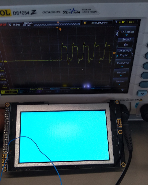
Image: Working LCD at 20 Mhz

Example code RA8875

Modified library .cpp

Modified library .h

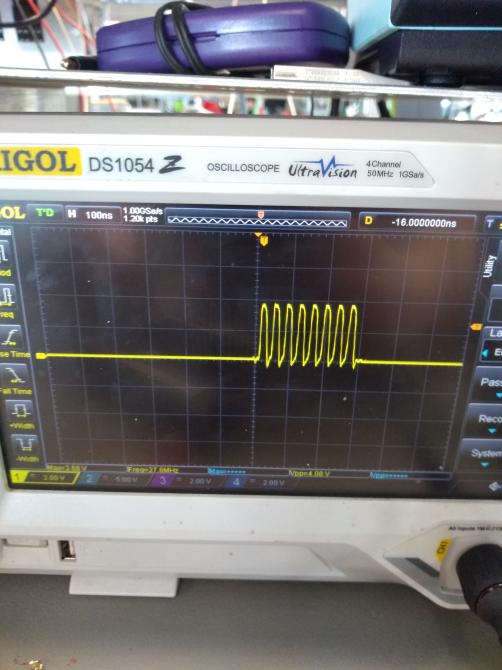
Edit by PPK: I add the pictures from paste pics to this post after I scaled and croped them.

Osci display with 20 MHz setup

Osci display with 30 MHz setup Osci display with 30 MHz setup

9
  • 1
    Sorry, I have no access to google drive and prefer not to log in. It would be better if you add the code and pictures direct to the question, in order to keep it if your google account would be deleted. --- The function you use is deprecated. --- Even if you set the clock speed to 84MHz, the send register must be filled with the picture data. That normally involves index computation and so on. After 8 Cycles the send register is empty, can you fill it within 8 CPU cycles? Or do you use DMA? I have some more ideas, but I'm busy at the moment. I'll come back. Commented Feb 9, 2021 at 13:55
  • 1
    When I saw the pictures, my first thought was: The 30 MHz signal is useless. The slope is not steep enough. But then I saw the blue wires (soldered?) to the board. Do you use them to connect the probes of the osci? That's not a good idea, as this long wires disturb reshape the signal at these frequencies; the wire acts as a low pass filter. Commented Feb 10, 2021 at 12:15
  • 1
    Try to put the probe direct to the clock pin and GND on the board if my assumption is correct, and you used the blue wires for the scope. If that does not change the signal form, then I would say the connection between the Due and the LCD is not sufficient for this frequency. Commented Feb 10, 2021 at 12:15
  • 1
    I thought about what you try to do: You had to configure the display to a clock frequencies of 250 MHz to achieve the refresh rate of 60 Hz with the given resolution. Then you try to deliver 60 frames per second over the SPI bus. That means the Due must be capable of generating or reading 60 frames with 768 kBytes per second and send it over the bus. I doubt the Due can handle this with its 84 MHz. So the demand of delivering 60 frames per second seems undoable to me. Commented Feb 10, 2021 at 12:27
  • 1
    The LCD has a 768 kB RAM to hold a picture frame. I asume it is possible to display it with 60 Hz but transfer only 25 frm/sec. But I'm not really sure if the RAM can be filled asynchrounously. Commented Feb 10, 2021 at 12:27

0

Your Answer

By clicking “Post Your Answer”, you agree to our terms of service and acknowledge you have read our privacy policy.

Browse other questions tagged or ask your own question.