2

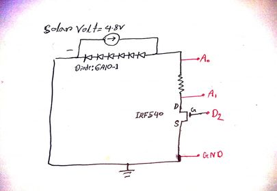
I need an IV curve for a solar panel. As far I know, solar-panel and Diode IV curve pretty much the same. Here, I am using diodes(6A10-1) as a solar-panel. Where each Diode voltage drops 0.6volt. I provide 4.8v across the diodes from a power supply and limited the current at 1amp of the power supply for acting like a solar panel. The number of diodes is 8 for a 4.8V drop. A 1-ohm resistor for measuring the current. I am using Arduino to measure the value of current and voltage by varies the MOSFET(IRF540) gate voltage. A low pass filter is connected between D2 and Mosfet Gate. A0 for measuring the solar voltage and Current, Id=A0-A1. But Arduino gives incorrect values of A1 and current, Id, and sometimes negative values with respect to a multimeter.

[circuit
const int V1 = A0;
const int V2 = A1;
float SolarVolt = 0.0;
float V1_VOLT = 0.0;
float V2_VOLT = 0.0;
float Id  = 0.0;
int V1_value = 0;
int V2_value = 0;
double gateVoltage=150; //For Gate volt
double mstep=5.1;
int GatePin=2;

void setup() {
  pinMode(GatePin,OUTPUT);
  Serial.begin(9600);
  pinMode(V1,INPUT);
  pinMode(V2,INPUT);
}

void loop() {
  analogWrite(GatePin,gateVoltage);
  gateVoltage=gateVoltage+mstep;
  Serial.print("GateVolt = ");
  Serial.print(gateVoltage);
  Serial.print("    ");
  if (gateVoltage <= 0) {
    mstep = 1;
  } else if (gateVoltage>=255){
    gateVoltage = 255;
    mstep = -1;
    delay(50);
  }

  V1_value = analogRead(V1);
  V1_VOLT = (V1_value * 5.0) / 1024.0;

  Serial.print("V1_VOLT= ");
  Serial.print(V1_VOLT);
  Serial.print("    ");

  V2_value = analogRead(V2); // for Id1
  V2_VOLT= (V2_value * 5.0) / 1024.0;

  Serial.print("V2_VOLT= ");
  Serial.print(V2_VOLT);
  Serial.print("    ");

  Id=V1_VOLT-V2_VOLT;

  Serial.print("ID= ");
  Serial.print(Id);
  Serial.println();

  delay(1000);
}
5
  • The garbage values like -0.5V,-0.02,-1.2V,+4V. I measured with a multimeter and the multimeter shows the correct values. PWM signal passed through a low pass filter, which gives a triangular DC voltage to the gate. No, I did not use any external DAC. Commented Nov 16, 2020 at 12:43
  • What values are you seeing? Have you measured the voltages with a multimeter? You do realise you are trying to send a PWM signal to the FET's gate, or do you somehow have a DAC on pin 2?
    – ocrdu
    Commented Nov 16, 2020 at 12:43
  • What raw Vx_value-s are you getting from the analogRead(Vx)? BTW Id = (V1-V2)/R.
    – ocrdu
    Commented Nov 16, 2020 at 12:53
  • Here R is one ohm. That's why Id = (V1-V2). Vx values are some times positive some times negative. But I didn't get the correct values with respect to multimeter. Commented Nov 18, 2020 at 9:07
  • Are you getting negative values for V1_value and V2_value?
    – ocrdu
    Commented Nov 18, 2020 at 12:34

1 Answer 1

2

Your current signal will also show PWM, so you will need to filter that before measuring. It would be much simpler if you could rearrange your circuit to put the sense resistor on the ground side of the MOSFET, since then you can use a simple RC filter and a single A0 measurement. Also, you wouldn't have to worry about the no-load voltage from the solar panel (when the MOSFET is off) going above the 5V limit of the A0 pin.

1
  • A low pass filter is connected between D2 and Mosfet Gate. Yes, I also told my faculty to put the sense resistor on the ground side of the MOSFET. But he told me to not connect it there. But I forget the reason. Thank you. Commented Nov 18, 2020 at 9:34

Your Answer

By clicking “Post Your Answer”, you agree to our terms of service and acknowledge you have read our privacy policy.

Not the answer you're looking for? Browse other questions tagged or ask your own question.