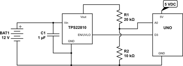
The most efficient is not to have a voltage divider at all. Or at least to only have a voltage divider when you actually need one.
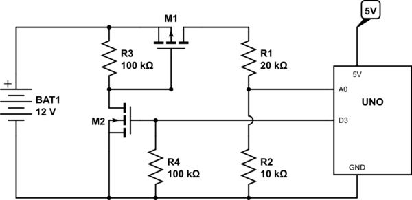
My preferred schematic is this:

simulate this circuit – Schematic created using CircuitLab
With this M1 is normally kept turned off by R3. When you want to take a measurement you turn on M2 by setting D3 HIGH (or whatever pin you attached it to) which pulls down the gate of M1 turning it on. This then connects the batter to the voltage divider R1/R2 and allows you to read the voltage at A0.
The voltage divider of 20k / 10k allows you to read up to 15V on the battery, and gives you an output impedance of 6.67kΩ which is within the recommended maximum of 10kΩ for the ATMega's ADC.
During "idle" times when M1 and M2 are both off the only current flowing is the minuscule leakage current through M2 tempered by the large 100kΩ resistor R3 (which itself pales into insignificance compared to the "off" resistance of M2 anyway).
Selecting M1 so that the ON resistance is very small (<0.1Ω) allows you to essentially ignore it in your calculations since that will be swamped by the tolerance of R1 and R2 anyway. M2 needs to be selected so that it is "logic level" (i.e, with a gate threshold V_GS well below 5V).
This double-FET arrangement should be used rather than just using an N-channel FET in the ground connection of the divider because when that simpler arrangement is turned off the Arduino will be seeing 12V directly connected to A0 which really is not good - you will kill the Arduino - so it is important that you switch the "high" side of the network not the "low" side, and to do that requires two FETs.


