0

I have a cheap ESP01 relay module and am using it with ESPEasy. I soldered the GPIO pin 16 to RST to allow deep sleep and that all works great.

However when the unit wakes up the relay flickers quite a bit. The application I had in mind was for a 12v fridge which draws quite a bit of current on start up. I think this flickering would damage the fridge compressor or controller pretty quickly, not to mention wearing out the relay itself.

I need the unit to wake up from deep sleep, and keep the relay in the off position, unless triggered by some external criteria.

Perhaps a capacitor would absorb the pin high voltage for a short period until it's booted? Trouble is that I don't really want to hack the module, I'll probably break something.

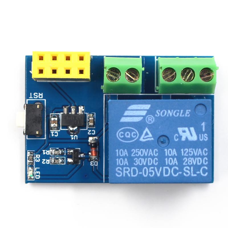
ESP01 Module

3
  • 1
    perhaps the starting point is to ask which IO pin does not change state when ESP01 wakes up ... that relay module may not be suitable for controlling a 12 V fridge (dependent on the current drawn by the fridge at startup)
    – jsotola
    Commented Aug 3, 2020 at 20:05
  • "Trouble is that I don't really want to hack the module", you already hacking the ESP-01 by connecting IO16 to RST, so what's the difficulty of adding a capacitor compare to the ESP-01 hack?
    – hcheung
    Commented Aug 4, 2020 at 15:16
  • well yes, that was already pretty difficult, and I succeeded in two out of three I've tried. But these relay boards are hard to come by where I am, so I'd want to be pretty confident to try that. I've already had to remove one smd resistor to get the thing to boot. each time I'm adding more risk of destroying the board
    – barrymac
    Commented Aug 4, 2020 at 22:02

2 Answers 2

2

The only two pins that don't glitch or change state during reset and boot are GPIO4 and GPIO5, and neither of them are brought out to the 2x4 header on an ESP-01. https://rabbithole.wwwdotorg.org/2017/03/28/esp8266-gpio.html

All of the other pins will make your relay click or chatter. Pick a different module, or try soldering a wire onto GPIO4 or 5. The boot time is ~ 150ms long, so it'd take a long time constant R-C circuit to filter it out, on the order of 1/2 second or more.

2

Apparently it's a pretty common issue for people using this board. There are a couple of solutions here that I will try: https://github.com/IOT-MCU/ESP-01S-Relay-v4.0/issues/1

The most non invasive one with Tasmoto firmware didn't work in my case. So I will try another pin and if that fails, bite the bullet and introduce a capacitor.

Your Answer

By clicking “Post Your Answer”, you agree to our terms of service and acknowledge you have read our privacy policy.

Not the answer you're looking for? Browse other questions tagged or ask your own question.