0

I'm working on my first Arduino project and I have a sensitivity issue.

I'm building a module to listen to an audio signal and to start the power source of my speaker with a relay. Everything seems to work fine, but if I drop the volume of my sound, the analog pin doesn't record values (at maximum volume, it peaks at around 50, which is not a lot).

I thought about getting a capacitor but I'm really not sure on what I should get and how the wiring should be done.

3
  • 2
    An analog input on an Arduino can only tolerate voltages from 0 to 5VDC. It can't tolerate negative voltages. Audio signals are AC signals. Their voltage changes rapidly from positive to negative. The negative voltages involved could damage your Arduino. It isn't safe to connect an audio source directly like this.
    – Delta_G
    Commented May 7, 2020 at 3:28
  • Hooo, thanks for that, I knew I'd learn something but not that I could have fryed my Arduino ;) Do you have any suggestions on what I could do and that is secure? I suppose that a diode bridge could fix that problem since I really don't care about the content of the signal? Commented May 7, 2020 at 3:53
  • If you only want to detect whether the signal existed or not, you can use a low-pass filter (basically through a diode and resistor to charge a capacitor) to give you a near-DC output, and bring it down to appropriate level, say 2.5v, and just read it through analogRead().
    – hcheung
    Commented May 7, 2020 at 11:29

2 Answers 2

1

it sounds like what you are wanting to do is to detect a minimum threshold of sound so that your speaker power source can be turned on when an audio signal is playing.

You need to amplify your signal while also avoiding voltages that exceed the maximum input specification and also don't go negative. One way to accomplish this is with an operational amplifier (op-amp) circuit. A specific type will accomplish all three requirements. An op-amp that is powered by a single-sided supply, for example +5V and ground, will prevent negative voltages and limit the maximum voltage exceeding what the Arduino can take.

For your application, you don't really care about making a high-quality audio amplifier. You care about not distorting the signal (music) that you are monitoring and detecting a threshold level. Op-amps are good because they have high impedance inputs (they don't draw much (or any) current from your music signal) and they work with few external components.

A classic text for learning about electronics is Horowitz and Hill. Alternatively, you can find references for circuit designs on-line with appropriate searches. For any op-amp that you buy, you can get a datasheet that tells you how to use it. The following reference goes into detail (maybe too much) about single supply op-amps.

Circuits (and search terms) that you might find useful are op-amp follower, single supply, bias, and capacitive coupling. You'll need to purchase components. A good supplier is DigiKey. DigiKey has an on-line catalog that allows you to do a parametric search to identify the components that you need. You'll need a breadboard, resistors, capacitors, and the op-amp in a dual-inline package (DIP).

One search filters the list of possibilities from tens of thousands to a reasonable number. The LM833 Datasheet here is a reasonable choice.

Test equipment, like a single generator and oscilloscope can be very helpful when building amplifiers. You might be able to digitize your amplified signal with your Arduino if you don't have access to test equipment.

1

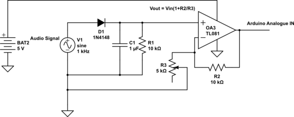
What you're looking for is called a peak detector, or probably better in your case - an envelope detector. Pass this through an op-amp with adjustable gain to let you tune your sensitivity. R3 - your potentiometer will let you adjust the sensitivity.Your gain will be

.

Set Vdd to 5V and common ground with your Arduino.

It's unlikely your audio source is generating too much voltage given you're saying its not registering - but in the unlikely event you're above 5V put a reverse biased Zener diode in parallel with your capacitor to clamp voltage to 5V

schematic

simulate this circuit – Schematic created using CircuitLab

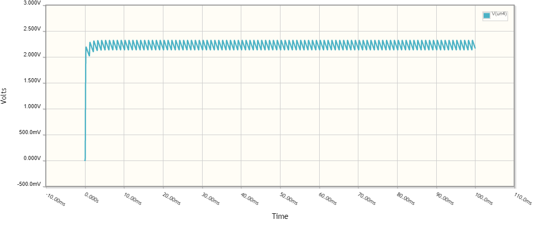
Hit simulate to see what playing with values does!

enter image description here

1
  • Sorry, it took sometime, everything was closed here... I just got my hand on all parts required. The problem that I now have is that the TL081 always give me the same reading on the arduino, even when I remove the jack from my board, I remove everything from my Vin but I kept having reading from the analogue IN. Have any idea on waht can cause that? Commented Jun 18, 2020 at 21:42

Your Answer

By clicking “Post Your Answer”, you agree to our terms of service and acknowledge you have read our privacy policy.

Not the answer you're looking for? Browse other questions tagged or ask your own question.