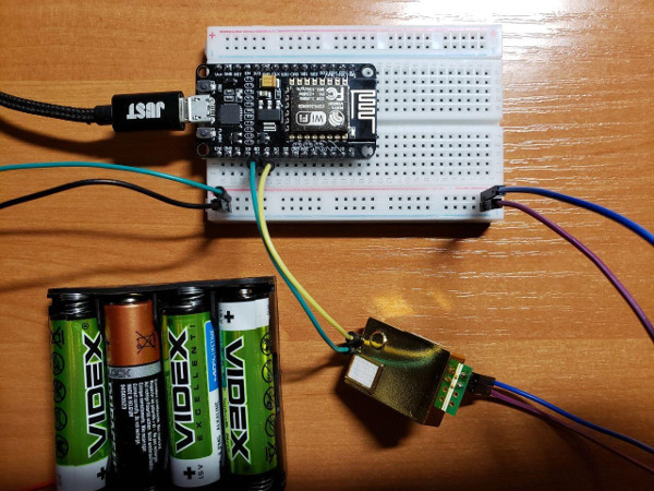
I'm trying to read data from MH-Z19B sensor to NodeMCU v2 board with a simple circuit like this.
Some key points, which could be not that obvious from picture:
- sensor has separate power supply of 4 AAs, providing ~5,5V
- sensor's TX connected to GPIO15 (TX D2) of NodeMCU
- sensor's RX connected to GPIO13 (RX D2) of NodeMCU
And here is my sketch:
const byte readCommand[] = {0xFF, 0x01, 0x86, 0x00, 0x00, 0x00, 0x00, 0x00, 0x79}; // according to datasheet
unsigned char response[9];

void setup() {
  // according to datasheet, sensor uses 9600 baud, 8 databits and 1 stopbit
  // with parity NONE, which I believe corresponds to default config SERIAL_8N1
  Serial.begin(9600);
}

void loop() {

    //  ... check if it is time to measure

    Serial.swap(); // switch to sensor

    Serial.write(readCommand, sizeof(readCommand));

    memset(response, 0, sizeof(response));

    int attempts = 5;
    int available = Serial.available();
    while(available < sizeof(response) && attempts > 0) {
        delay(100);
        attempts--;
        available = Serial.available();
    }

    Serial.readBytes(response, sizeof(response));

    Serial.swap(); // switch back to console

    // print out the response in hex
    for (int i = 0; i < sizeof(response); i++) {
      Serial.print(String(response[i], HEX));
      Serial.print("   ");
    }

    // ...process the response according to protocol
}
The Problem
For some reason after sending command to serial I get an answer exactly the same as command is although the structure of answer expected to be different. Of course datasheet says nothing about situations like this.
Expectation
ff 86 .. .. 0 0 0 0 CRC
Reality (same bytes I sent as a command)
ff 1 86 0 0 0 0 0 79
Other notes:
- I got exactly the same when tried to use SoftwareSerial with D1 & D2 pins
- connecting TX to RX respectively on both sensor and MCU results in reading failure
- I tried to pull everything while available from serial, there are only my expected 9 bytes
- my soldering skills are far from ideal, but I'm pretty sure tx/rx on the sensor are connected properly
I'm new to all this stuff, so it is completely possible that there is ridiculously silly, but crucial mistake, so would appreciate any help on this. And I understand that sensor also has additional interfaces to obtain the value, but as I mentioned I'm a newbie and wanted to familiarize myself with UART as this is something new for me.
UPD 1:
I didn't use level conversion for sensor output as datasheet says:

Assuming this I thought that sensor provides logical level conversion itself. Did I get it wrong?
UPD 2:
I got back to proper TX - RX connection just to check out what is going on exactly to describe that "reading failure" problem with more details. It seems that Serial.available() returns 0 after I send command so this loop gets stopped after 5 attempts:
while(available < sizeof(response) && attempts > 0)


reading failurecase and my assumptions I took from datasheet which made me think I don't need 3,3 level conversion.