0

I have a problem with stepper motor direction.

I want to change the direction of the stepper motor rotation, when the stepper motor shaft is stuck.

For example, when I hold the shaft of the stepper motor with my hand, the direction should change.

How can I do it? Someone told me you should calculate the current, but I don't know how to do this?

My material components:

  • Arduino
  • stepper motor gearbox 12 V
  • ULN 2003A
6
  • 1
    When motors stuck their current draw increases, you can sense that increase in the current (with any current sense method you see fit) and then change the rotation of the motor. Commented Oct 18, 2019 at 10:14
  • I now this discuss but I dont now how can I do it I have no idea circuit or cod for it can you help me more ? i need it Commented Oct 18, 2019 at 10:22
  • in Face if you have seen the air conditioner splite Opereting system stepper motor it rotats the some way for 360 Degree but when shaft stuck the direction change I want do this Commented Oct 18, 2019 at 10:27
  • If you haven't any knowledge about electronics I'm afraid you will fail in that project. You first had to learn what current is, how current is measured ( over a shunt or by heating a wire or whatever). You possibly must compute a mean value. You had to learn how to use the right ground potential and so on. And there are issues with the current that is drawn by the stepper before each step to overcome the inertia of the rotor. But if you're only supossed to change the direction of the rotation at a define location you could use a switch at that location. That's much easier. Commented Oct 18, 2019 at 10:41
  • I now about electrinics .but now a lot .but you Idea is very nice about swiching at that location but I have no any place for it I wnat works like air conditoner Commented Oct 18, 2019 at 10:48

1 Answer 1

1

When motors stuck their current draw increases, you can sense that increase in the current and then change the rotation of the motor. The simplest way to measure current is with using a shunt resistor, for sensing high currents, current sensors based on hall effect sensors is usually used. ACS712 is one example.

How to sense current using a shunt?

Basically we're measuring the voltage drop over a resistor (RS), but the voltage drop is too small for Arduino to measure so we need an opamp to "amplify" the input:
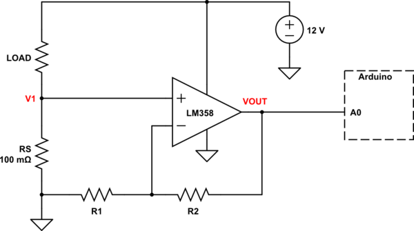
schematic

simulate this circuit – Schematic created using CircuitLab

The schematic above is the simplest way to measure the voltage drop at "LOW SIDE", there is differential mode and "HIGH SIDE" measurement methods.

The gain of opamp can be set with resistors and this formula:

VOUT = (1 + R2/R1) * V1

The output of opamp then can be calculated to get current using ohm's law:

I = V / R

A simple code to calculate current:

int rawAnalog;
float voltageDrop;
int resistor = 0.1;
float current;

void setup() {
  pinMode(A0, OUTPUT);
}

void loop() {
  rawAnalog = analogRead(A0); // Read A0 input
  voltageDrop = (rawAnalog * 5) / 1024; // Convert the raw value to voltage
  current = voltageDrop / resistor; // calculate the current
}

Bonus: INA219 is an easy to use high-side I2C module which can measure both current and voltage.

9
  • I good idea.can give a circuit for hall effect sensor ?the hall effect sensor must connect to uln 2003 or arduino pin for send commend Commented Oct 18, 2019 at 10:53
  • This would be a good solution if he uses a "normal" DC-Motor. A Stepper has at least two groups of coils, each of them has its own plus and minus connection. And the current is not constant while stepping. It even gets more complicated if the stepper works with micro steps. Commented Oct 18, 2019 at 10:54
  • @PeterPaulKiefer he can measure the overall current at the power source, no need to measure group of coils... Commented Oct 18, 2019 at 10:56
  • Yes that's correct. You could measure the current the controller needs to supply the motor. But depending on the load there are high peaks. Controller IC can limit that current to protect themselves. If @Rayan_skofw had no experience which such things he/she get's easily frustrated. So I would suggest to him to use switches to check if the rotation is a a defined point and then invert the direction. Not the measuring is the problem, IMHO you can not easily distinguish between the normal stepper starts and the end condition if you only check the current. Commented Oct 18, 2019 at 11:08
  • 1
    Thanks all you guys. I want do it now what i learn here Commented Oct 18, 2019 at 11:20

Your Answer

By clicking “Post Your Answer”, you agree to our terms of service and acknowledge you have read our privacy policy.

Not the answer you're looking for? Browse other questions tagged or ask your own question.