0

I have scavenged an industrial servo with its attached ballscrew linear actuator from an old large format scanner, and I am trying to figure out how to make a 'servo drive' aka 'servo driver' aka 'servo controller'.

I'm a total novice at arduino, and am mostly a copy/paste coder - so of course this makes my goal harder.

I can find a lot of information on how to read a simple AB offset encoder that needs four wires to work, but the encoder I have has eight wires:

A+, A-, B+, B-, Z+, Z-, +5v, 0v(aka GND)

With +5v supplied to it's wire and GND connected to 0v, rotating the motor shaft by hand, my meter reads:

  • A+: +3.97v as the 'high' and +.036v as 'low'
  • A-: same
  • B+: same
  • B-: same
  • Z+: same - but only goes high at one location on the 360 degree
    rotation
  • Z-: same - but only goes high at one location on the 360 degree rotation - the same location as Z+

NOTE: Both Z pulses coincide with pulses on A+, B+, and B- ... but those are NOT coincident on A-. So maybe A- has the Z+/- trigger in it's place? I don't know. It was VERY challenging to stop rotating the shaft AT a pulse because of the tiny size of the divisions.

All voltages seen by my digital multimeter were positive voltages.

I do not understand how to properly use the encoder with so many wires. I can sort of understand that the positive and negative are probably opposite signals from each other, sort of error protection or something? I know that the Z= and Z- are roattion counters at either 90, 180, or some other offset angle to allow ticking full rotations. But am unsure about this all and am reading a lot of material that is beyond me. I'm stumped.

I can install the following code on an UNO and the UNO reads the encoder just fine off the A+ and B+ lines, with increasing count for one direction of rotation and decreasing count for the other direction. So it is reflecting the movement as it should...

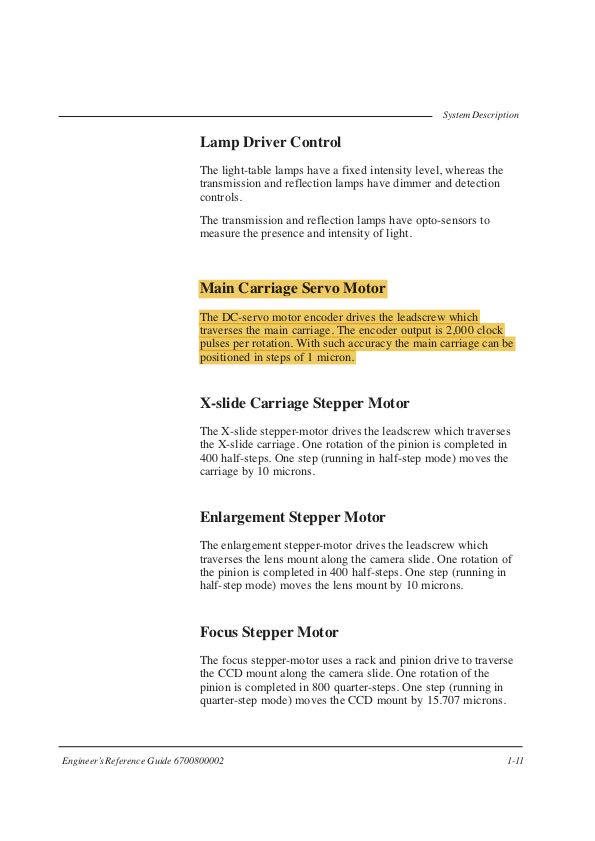
BUT- I am getting 8000 pulses per shaft revolution rather than the 2000 pulses per revolution in the documentation. So something's not right here. I should see 2000 pulses per revolution... is this because of the lack of use of the other wires? Or something else?

Code i'm using for just A+ and B+:

    /*
*Quadrature Decoder 
*/
#include "Arduino.h"
#include <digitalWriteFast.h> 

// Quadrature encoders
// Left encoder
#define c_LeftEncoderInterruptA 0
#define c_LeftEncoderInterruptB 1
#define c_LeftEncoderPinA 2
#define c_LeftEncoderPinB 3
#define LeftEncoderIsReversed

volatile bool _LeftEncoderASet;
volatile bool _LeftEncoderBSet;
volatile bool _LeftEncoderAPrev;
volatile bool _LeftEncoderBPrev;
volatile long _LeftEncoderTicks = 0;

void setup()
{
  Serial.begin(9600);

  // Quadrature encoders
  // Left encoder
  pinMode(c_LeftEncoderPinA, INPUT);      // sets pin A as input
  digitalWrite(c_LeftEncoderPinA, LOW);  // turn on pullup resistors
  pinMode(c_LeftEncoderPinB, INPUT);      // sets pin B as input
  digitalWrite(c_LeftEncoderPinB, LOW);  // turn on pullup resistors
  attachInterrupt(c_LeftEncoderInterruptA, HandleLeftMotorInterruptA, CHANGE);
  attachInterrupt(c_LeftEncoderInterruptB, HandleLeftMotorInterruptB, CHANGE);
}

void loop()
{ 
  Serial.print("Encoder Ticks: ");
  Serial.print(_LeftEncoderTicks);
  Serial.print("  Revolutions: ");
  Serial.print(_LeftEncoderTicks/2000.0); //2000 Counts Per Revolution, per the engineering manual
  Serial.print("\n");
}


// Interrupt service routines for the left motor's quadrature encoder
void HandleLeftMotorInterruptA(){
  _LeftEncoderBSet = digitalReadFast(c_LeftEncoderPinB);
  _LeftEncoderASet = digitalReadFast(c_LeftEncoderPinA);

  _LeftEncoderTicks+=ParseEncoder();

  _LeftEncoderAPrev = _LeftEncoderASet;
  _LeftEncoderBPrev = _LeftEncoderBSet;
}

// Interrupt service routines for the right motor's quadrature encoder
void HandleLeftMotorInterruptB(){
  // Test transition;
  _LeftEncoderBSet = digitalReadFast(c_LeftEncoderPinB);
  _LeftEncoderASet = digitalReadFast(c_LeftEncoderPinA);

  _LeftEncoderTicks+=ParseEncoder();

  _LeftEncoderAPrev = _LeftEncoderASet;
  _LeftEncoderBPrev = _LeftEncoderBSet;
}

int ParseEncoder(){
  if(_LeftEncoderAPrev && _LeftEncoderBPrev){
    if(!_LeftEncoderASet && _LeftEncoderBSet) return 1;
    if(_LeftEncoderASet && !_LeftEncoderBSet) return -1;
  }else if(!_LeftEncoderAPrev && _LeftEncoderBPrev){
    if(!_LeftEncoderASet && !_LeftEncoderBSet) return 1;
    if(_LeftEncoderASet && _LeftEncoderBSet) return -1;
  }else if(!_LeftEncoderAPrev && !_LeftEncoderBPrev){
    if(_LeftEncoderASet && !_LeftEncoderBSet) return 1;
    if(!_LeftEncoderASet && _LeftEncoderBSet) return -1;
  }else if(_LeftEncoderAPrev && !_LeftEncoderBPrev){
    if(_LeftEncoderASet && _LeftEncoderBSet) return 1;
    if(!_LeftEncoderASet && !_LeftEncoderBSet) return -1;
  }
}

. . . Can someone explain the function of, and how to use, all eight wires? Explain why I'm getting 4X the counts that I should with that code above? PLEASE? . . .

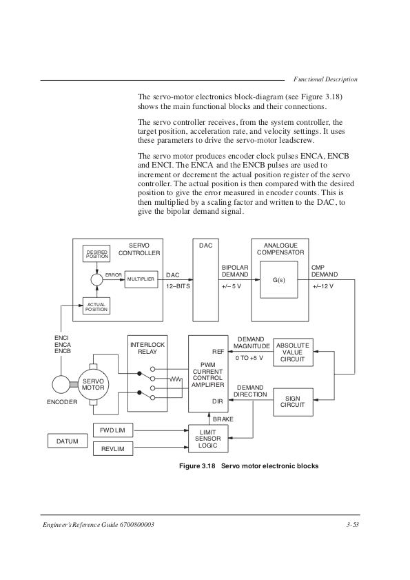
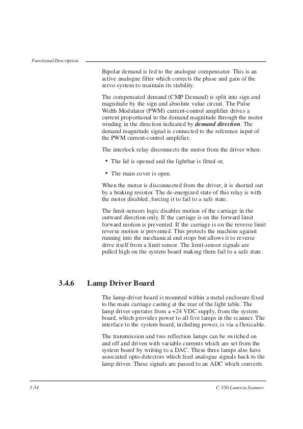
I'm posting images of the pages from the machine's engineering handbook that have info about the servo and encoder. The info there shows that it was more or less controlled like an RC servo from the mainboard's perspective - just PWM. But it had the drive/driver/controller parts right on the mainboard of the machine.

If it will be of use I can post pictures of the encoder board itself, but at this point I did not think that necessary.

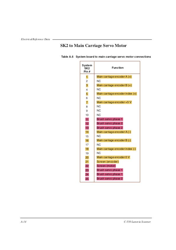
Piniout of connector Servo encoder resolution Specs part 1 Specs part 2

4
  • 1
    connect +5V and GND to the encoder ... use a voltmeter to monitor one output pin ... turn servo slowly by hand
    – jsotola
    Commented Aug 25, 2019 at 5:46
  • Wire identity is already established. See picture posted of pinout table.
    – 111936
    Commented Aug 25, 2019 at 8:55
  • if that is true, then why does your post have the following statement? ... positive and negative are probably opposite signals from each other, sort of error protection or something
    – jsotola
    Commented Aug 25, 2019 at 21:46
  • I put that in my post because I have read a few web pages that say that this is how some encoders work. And you didn't quote the question mark immediately following the word 'something". I have added voltage readings for all wires to the question.
    – 111936
    Commented Aug 25, 2019 at 22:49

2 Answers 2

2

I had some trouble figuring this out too. I did some more googling and found this site below via an Arduino forum post: 8 wire connection for quadrature encoder, differential wiring

Here is what they say:

"These terms refer not to the waveforms of signals, but instead to the way the signals are wired.

Single-ended wiring uses one signal wire per channel and all signals are referenced to a common ground.

TTL and Open Collector are types of single-ended wiring.

Differential wiring uses two wires per channel that are referenced to each other. The signals on these wires are always 180 electrical degrees out of phase, or exact opposites. This wiring is useful for higher noise immunity, at the cost of having more electrical connections. Differential wiring is often employed in longer wire runs as any noise picked up on the wiring is common mode rejected."

So basically we have our Power supply wire and ground, and 2 wires per signal (A+/A-, B+/B-, Z+/Z-).

2 + 6 wires = 8 wires

Now all I have to figure out is how to connect those 6 wires to an Arduino. I get how to connect the A+, B+, Z+ signals on 3 interrupt pins, now I'm just wondering if the other 3 (A-, B-, Z-) should be connected to 3 more interrupt pins.

1
0

You have already found out, how the encoder works (basically like any other rotary encoder, only with more outputs for different angle values). That is great work.

You get a value 4 times as big because of 2 little mistakes:

  1. When you use attachInterrupt(), you set it to trigger on a CHANGE of the line. One pulse consists of 2 changes (for example LOW to HIGH and then HIGH to LOW). So the interrupt get's triggered twice per encoder pulse. That's a factor of 2 for the resulting value.

  2. You attach an interrupt to both of the lines, but both lines output one pulse per one encoder tick. So the value get's incremented twice per tick, what means another factor of 2. You only need an interrupt on one of the lines. The other line is only there to indicate the direction of the rotation. When the interrupt for the first line triggers, you should check the value of the second line. If it is HIGH, the encoder is rotating in one direction. If it is LOW, it rotates in the oposite direction. The lines are internally connected to little buttons/switches, that are fixed to the casing with a little offset between then. They get activated by little nubs, that are connected to the axis. Depending on from which direction the nub comes during a rotation, the first or the second button/switch will get activated first. A little after that, also the second switch will activate. So you can monitor one line, and if a pulse starts on it, you check if there already is a pulse on the other line. If yes, the other line was activated first.

So all in all this results in the factor 4 in the encoder results.


Note, that your ParseEncoder() function is a little redundant and overcomplicated. In the inner if statements you check for some values, that cannot happen in there because of the outer if statement. But this function will reduce itself to simply one if statement (or less, if you use the value directly without if), since with the above, you only need to check the value of 1 line.

4
  • OK - learning that quadrature encoding can be read as 1x, 2x, or 4x per rotor mark is not the same as learning how this particular encoder works. Using A+ and B+ I count all four possible ticks as a rotor mark passes. Z+ would theoretically let me count full rotations and serve as a check against missed triggers by the A+ interrupt - if I could figure out how to interrupt interrupts because Z+ rises at the same time that A+ rises. Got it. But A- and B- and Z- remain unexplained/not understood. Not that I MUST use them, but I do want to understand what they are there for if I can.
    – 111936
    Commented Aug 27, 2019 at 1:57
  • Unfortunately I cannot help you with undocumented hardware, as I cannot test it myself. You yourself have to analyse how the outputs behave. If you make a diagram, how exactly the outputs behave, I can try to guess the function, but not more.
    – chrisl
    Commented Aug 28, 2019 at 10:23
  • Fair enough. My assumption (and reason for posting) was that someone here in the stack would read "8 wire encoder" and then read my reported voltages .. and be familiar with similar encoders enough to illuminate me on what the other wires are for and maybe even how to use them. I still have a sneaking suspicion they are a redundancy to error-check with but can't be sure with my almost non-existent knowledge of these things.
    – 111936
    Commented Aug 29, 2019 at 8:09
  • Still hoping someone will explain the other three wires: A-, B-, and Z-. Can't mark this answer as the answer without having the first part of the question addressed.
    – 111936
    Commented Sep 4, 2019 at 1:40

Your Answer

By clicking “Post Your Answer”, you agree to our terms of service and acknowledge you have read our privacy policy.

Not the answer you're looking for? Browse other questions tagged or ask your own question.