Often in software development, the code is the documentation. The merits of this are debated ad nauseam elsewhere.
As you have provided a link to the GitHub repository of the library you are using, you have all you need, though the provided utility/docs path doesn't fully document the I2C interface.
The function prototype (that is, the function, its return type, and parameters, but without the actual code) is found in header files which usually have the .h suffix.
Since you have an LCD with a I2C interface, you can look at the GitHub repo for the file LiquidCrystal_I2C.h
Within this file, you can see that the class is defined with name LiquidCrystal_I2C and has multiple constructors, each with a different list of parameters. The particular class constructor used is the one that matches the count and type called in your declaration of the object of that class.
The code in the header file is well documented. The first prototype listed includes good commenting:
/*!
    @method
    @abstract   Class constructor.
    @discussion Initializes class variables and defines the I2C address of the
    LCD. The constructor does not initialize the LCD.

    @param      lcd_Addr[in] I2C address of the IO expansion module. For I2CLCDextraIO,
    the address can be configured using the on board jumpers.
    */
   LiquidCrystal_I2C (uint8_t lcd_Addr);
   // Constructor with backlight control
   LiquidCrystal_I2C (uint8_t lcd_Addr, uint8_t backlighPin, t_backlighPol pol);
This block shows the first 2 constructor options: With a uint8_t type that defines the I2C address of an I/O expansion module (which is what many "LCD backpacks" are -- that, or shift registers), and one with an I2C address, a backlight pin, and the polarity of the backlight.
Proceeding down, we find the one with 10 parameters, which is what you ended up using:
  /*!
    @method
    @abstract   Class constructor.
    @discussion Initializes class variables and defines the I2C address of the
    LCD. The constructor does not initialize the LCD.

    @param      lcd_Addr[in] I2C address of the IO expansion module. For I2CLCDextraIO,
    the address can be configured using the on board jumpers.
    @param      En[in] LCD En (Enable) pin connected to the IO extender module
    @param      Rw[in] LCD Rw (Read/write) pin connected to the IO extender module
    @param      Rs[in] LCD Rs (Reset) pin connected to the IO extender module
    @param      d4[in] LCD data 0 pin map on IO extender module
    @param      d5[in] LCD data 1 pin map on IO extender module
    @param      d6[in] LCD data 2 pin map on IO extender module
    @param      d7[in] LCD data 3 pin map on IO extender module
    */
   LiquidCrystal_I2C(uint8_t lcd_Addr, uint8_t En, uint8_t Rw, uint8_t Rs,
                     uint8_t d4, uint8_t d5, uint8_t d6, uint8_t d7 );
   // Constructor with backlight control
   LiquidCrystal_I2C(uint8_t lcd_Addr, uint8_t En, uint8_t Rw, uint8_t Rs,
                     uint8_t d4, uint8_t d5, uint8_t d6, uint8_t d7,
                     uint8_t backlighPin, t_backlighPol pol);
That last constructor is used to override the default pin mappings from the I/O Expander to the LCD. This is tricky -- what were the mappings based on? An I/O expander is basically a way to access multiple pins on an external chip through a single two-wire interface (I2C). How an LCD is connected depends on what pins of the I/O Expander are connected to which pins of the LCD. There is not a formal standard, though there may be convention.
Reading the GitHub page, you see that this is a
Clone of the new liquid crystal library from: https://bitbucket.org/fmalpartida/new-liquidcrystal
Following that link takes us to some kind of documentation, noting that one of the connection types is:
I2C IO bus expansion board with the PCF8574* I2C IO expander ASIC such as I2C LCD extra IO.
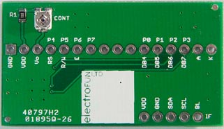
A link to that hardware is helpfully provided! We can follow the link to see that the hardware is discontinued, but helpfully documented with some schematics and PCB layouts that tell us which pins of the I/O expander are connected to which pins of the LCD:

P0 is pin 0 of the I/O expander -- the top row are the I/O expander pins. Vo, RS, R/W, etc. are the LCD pins.
LCD Pin  |  I/O Expander Pin
     En  |  P4
    R/W  |  P5
E (rst)  |  P6
     D4  |  P0
     D5  |  P1
     D6  |  P2
     D7  |  P3
(And the backlight is a passthrough pin, not on the I/O Expander. It appears the definition of the backlight pin and polarity refer to I/O Expander pins.)
This is the point where you have to find out if the I/O expander on your purchase has the same pinout as the product for which this library was written.
Your "working" instance is called as (with annotations to the constructor being called)
LiquidCrystal_I2C lcd(
  0x27,       // lcd_Addr
  2,          // En (enable pin)
  1,          // Rw (read/write pin)
  0,          // Rs (reset pin)
  4,          // d4 (data)
  5,          // d5 (data)
  6,          // d6 (data)
  7,          // d7 (data)
  3,          // backlight
  POSITIVE    // backlight polarity
);
This indicates that the I/O expander on your LCD does not have the same pin connections as that for which the library was written, which is why you had success only when remapping them in the constructor.
All that to just re-state the hair-pulling you had to do!
The actual functions available are noted to be:
This library provides the same interface to applications as the LiquidCrystal library sourced by the Arduino SDK.
But to be absolutely sure, you can also see their prototypes in the header file: https://github.com/fmalpartida/New-LiquidCrystal/blob/master/LCD.h
It provides scrolling, blinking, enable/disable, etc.

