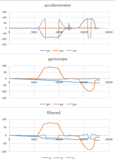
I've been playing with a GY521 breakout recently with the MPU6050 chip on it, though i've hit a bit of a problem that I can't quite work out
I know when I rotated the board I rotated ~90 degrees about the Y axis, and using the sensitivity numbers from the datasheet (131) and integrating i've managed to get something that looks believable from the gyroscope, but am having problems with the accelerometer.
From a number of sources, this being one of them, I've managed to get the three equations seen on here, however when I apply them to either the raw or scaled data (as they're scalers is shouldn't make a difference?) I get a set of data that varies from 0 to 90, but only on the X and Z axes, while nothing happens to the Y.
Updated to include code:
#include "I2Cdev.h"
#include "MPU6050.h"
#include "Wire.h"

MPU6050 accelgyro;

int16_t ax, ay, az, gx, gy, gz;

double timeStep, time, timePrev;
double arx, ary, arz, grx, gry, grz, gsx, gsy, gsz, rx, ry, rz;

int i;
double gyroScale = 131;

void setup() {

  Wire.begin();
  Serial.begin(9600);
  accelgyro.initialize();

  time = millis();

  i = 1;

}

void loop() {

  // set up time for integration
  timePrev = time;
  time = millis();
  timeStep = (time - timePrev) / 1000; // time-step in s

  // collect readings
  accelgyro.getMotion6(&ax, &ay, &az, &gx, &gy, &gz);

  // apply gyro scale from datasheet
  gsx = gx/gyroScale;   gsy = gy/gyroScale;   gsz = gz/gyroScale;

  // calculate accelerometer angles
  arx = (180/3.141592) * atan(ax / sqrt(square(ay) + square(az)));
  ary = (180/3.141592) * atan(ay / sqrt(square(ax) + square(az)));
  arz = (180/3.141592) * atan(sqrt(square(ay) + square(ax)) / az);

  // set initial values equal to accel values
  if (i == 1) {
    grx = arx;
    gry = ary;
    grz = arz;
  }
  // integrate to find the gyro angle
  else{
    grx = grx + (timeStep * gsx);
    gry = gry + (timeStep * gsy);
    grz = grz + (timeStep * gsz);
  }

  // apply filter
  rx = (0.1 * arx) + (0.9 * grx);
  ry = (0.1 * ary) + (0.9 * gry);
  rz = (0.1 * arz) + (0.9 * grz);

  // print result
  Serial.print(i);   Serial.print("\t");
  Serial.print(timePrev);   Serial.print("\t");
  Serial.print(time);   Serial.print("\t");
  Serial.print(timeStep, 5);   Serial.print("\t\t");
  Serial.print(ax);   Serial.print("\t");
  Serial.print(ay);   Serial.print("\t");
  Serial.print(az);   Serial.print("\t\t");
  Serial.print(gx);   Serial.print("\t");
  Serial.print(gy);   Serial.print("\t");
  Serial.print(gz);   Serial.print("\t\t");
  Serial.print(arx);   Serial.print("\t");
  Serial.print(ary);   Serial.print("\t");
  Serial.print(arz);   Serial.print("\t\t");
  Serial.print(grx);   Serial.print("\t");
  Serial.print(gry);   Serial.print("\t");
  Serial.print(grz);   Serial.print("\t\t");
  Serial.print(rx);   Serial.print("\t");
  Serial.print(ry);   Serial.print("\t");
  Serial.println(rz);

  i = i + 1;
  delay(50);

}
Results:

Strikes me as a little odd, as I was expecting only a rotational change in Y. Any suggestions?
