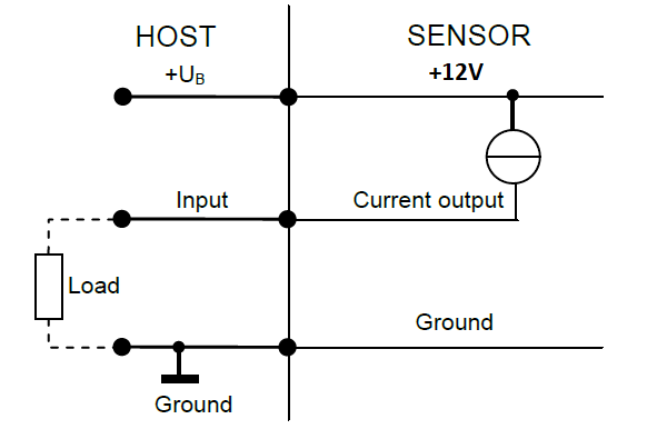
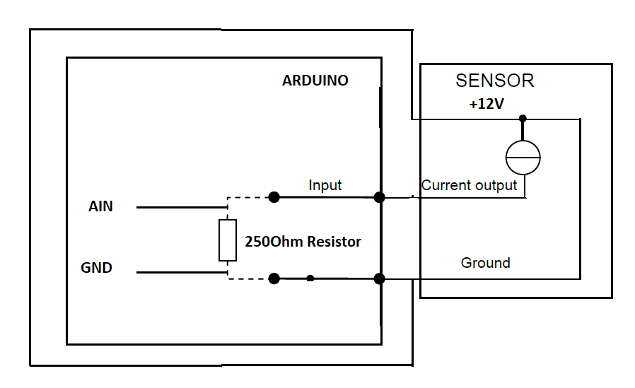
The connection diagram is showing the sensor being powered by a host that runs at 12v. Normally the host would provide the power. However, you provide the power yourself from another source. So you don't need power from the host, so you do not connect the 12v to the host.
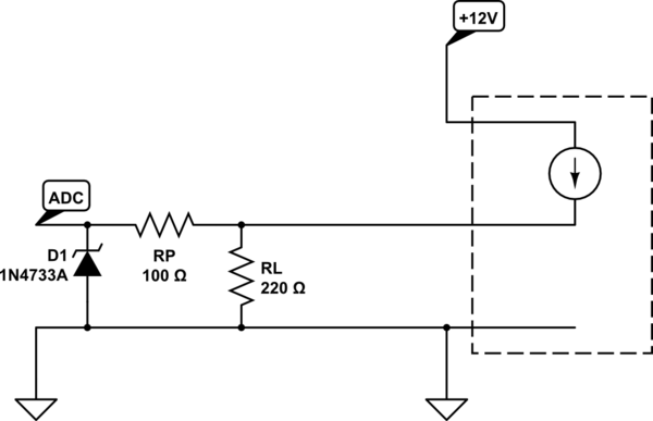
All you need is the signal and the ground (along with a load resistance to convert the current into a voltage, and maybe some over voltage protection on the signal in case the load resistance becomes disconnected or fails in some other way).

simulate this circuit – Schematic created using CircuitLab
In that example RL is the "Load" resistor and is calculated as the nearest common resistance value that gives, with 20mA (assuming a standard 4-20mA sensor) through it, close to 5V across it without going over. In this case, 4.4V, which is good. RP is a "protection" resistor to prevent damage to the sensor should the load resistor fail, which would give 12V (though limited in current) across the zener diode D1. It just limits the current that can flow through D1 and be pulled by an effective short circuit across the sensor's output when D1 fails over (if it ever does). D1 is there to prevent the ADC from ever seeing any more than 5.1V in the event of a problem.


