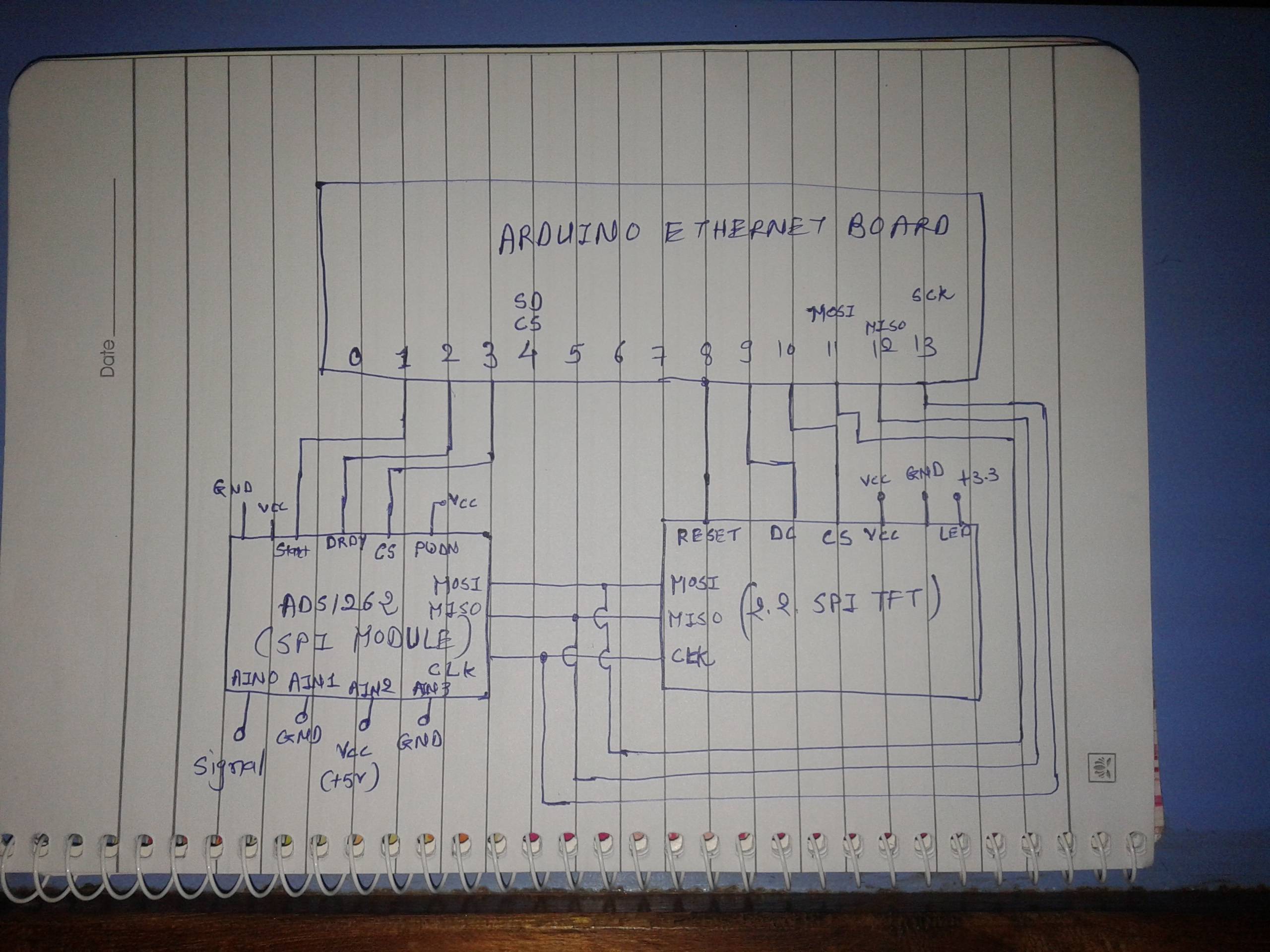
I am interfacing two SPI slave module i.e. ADS1262 and 2.2 SPI TFT with the Arduino Ethernet board.
When I test each device on its own it works. Initially, I interfaced the TFT to the Arduino and it is working fine. Likewise, the example code of ADS1262 is working fine when I am running it alone.
So after successfully running the TFT alone, I then wire-up the ADS1262, add the corresponding code, however the ADS1262 doesn't seem to respond.
I think the issue may be related to the ADS1262_CS or ADS1262_START or ADS1262_DRDY pin sequence to access the ADS1262.
I have used the ProtoCentral_ads1262 library from GitHub and have used the example code.
From Comments:
We have already reserved D10 for Ethernet Controller and D4 for SD Chip select. The issue is, how to communicate both of them, one by one. I can access one of them only when code is prepare for both devices.
// Portion of the code is given here

// https://github.com/adafruit/Adafruit_ILI9341 library used for TFT

// Code start from here


for(j=initvalue;j<=finalvalue;j+=x)
{

      dacvalue=((j*5)/65535);

      writeValue(j);

      tft.fillRect(30,150,70,28,ILI9341_BLACK);

      tft.setCursor(30,150);

      tft.println(dacvalue,3); // dac value is showing on TFT

      Serial.println(dacvalue,3);

// ADS1262 is need to communicate here as per https://github.com/Protocentral/ProtoCentral_ads1262 library

// Which pins are need to control here to communicate with ADS1262???

      volatile int p,data;

      if((digitalRead(ADS1262_DRDY_PIN)) == LOW)               // monitor Data ready(DRDY pin)
     {
       SPI_RX_Buff_Ptr = PC_ADS1262.ads1262_Read_Data();      // read 6 bytes conversion register
       Responsebyte = true ;
     }

      if(Responsebyte == true)
      {
       for(p = 0; p <5; p++)
      {
        SPI_RX_Buff[SPI_RX_Buff_Count++] = *(SPI_RX_Buff_Ptr + p);
      }
      Responsebyte = false;
      }

       if(SPI_RX_Buff_Count >= 5)
      {
        ads1262_rx_Data[0]= (unsigned char)SPI_RX_Buff[1];  // read 4 bytes adc count
        ads1262_rx_Data[1]= (unsigned char)SPI_RX_Buff[2];
        ads1262_rx_Data[2]= (unsigned char)SPI_RX_Buff[3];
        ads1262_rx_Data[3]= (unsigned char)SPI_RX_Buff[4];


        uads1262Count = (signed long) (((unsigned long)ads1262_rx_Data[0]<<24)|((unsigned long)ads1262_rx_Data[1]<<16)|(ads1262_rx_Data[2]<<8)|ads1262_rx_Data[3]);//get the raw 32-bit adc count out by shifting
        sads1262Count = (signed long) (uads1262Count);      // get signed value
        Serial.println("sads1262Count:");
        Serial.println(sads1262Count);
        resolution = (double)((double)VREF/pow(2,31));       //resolution= Vref/(2^n-1) , Vref=2.5, n=no of bits
        Serial.println(resolution,15);
        volt_V      = (resolution)*(float)sads1262Count;     // voltage = resolution * adc count
        volt_mV   =   volt_V*1000;                           // voltage in mV
     tft.setCursor(166,150);
     tft.println(volt_mV,3); } //not printed on TFT
In above code, ADS1262 is not activated so not giving value on serial window or TFT.
How to activate the ADS1262 module.

