2

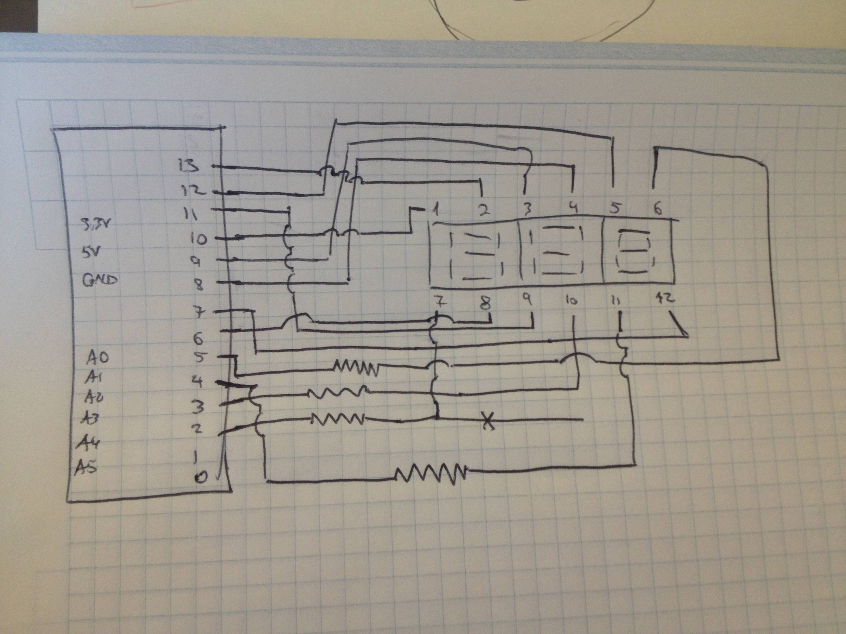
I am new to Arduino. I have been trying to connect a 7 segment display (3 digits) to my Arduino and I was successful, but I am not doing any connection to ground. I do not find the data sheet so I am not sure if this connection is well done. My doubt is: Is the connection to ground necessary? Or how do Arduino pins work? I am using 12 pins of the Uno to do the set up.

Thanks

My set up is the following: enter image description here

7
  • Is the display common anode or common cathode? Commented Jun 19, 2014 at 1:30
  • To tell you truth @IgnacioVazquez-Abrams, I really don't know. How can I verify this? is there any special annotation on the device? or any special behavior? Commented Jun 19, 2014 at 1:38
  • Which pins control which display lights up and which ones control the segments, and which one do you have to apply the positive voltage to? (Also, your pin notation is incorrect; pin 1 is at the bottom left and they go up counter-clockwise.) Commented Jun 19, 2014 at 2:04
  • Great, thanks for the help and for the correction on my notation. Tomorrow I will keep posting the things you are requesting once I verify on the Arduino how the display is working. Commented Jun 19, 2014 at 2:34
  • 1
    I second @jfpoilpret. The pins on the arduino can only provide/sink 40mA of current. I also see you added the resistors to the digits instead of the segments. That way, the more segments are on, the dimmer the display will be. It's better to put the resistors on the segments. Also use a resistor value that will limit the current to no more than 5mA per segment. That way, even if all segments are lit, the total current will be below 40mA.
    – Gerben
    Commented Jun 21, 2014 at 12:05

1 Answer 1

1

I don't know exactly how your display is wired exactly, but it is certain that some sort of multiplexing is going on, since A: there is no wired ground, and B, you are controlling more LED's than you have pins going to the display.

Multiplexing manages this by using some trickery and persistence of vision. The pins for each part of the segment are all wired together. For example, the top segment on each of the three segments are all connected to one arduino pin. The common anode/cathode (depending on your specific display) for each of your three displays are wired separately however. Turning only one of the common pins on will cause only one display to function when the other pins set which segments are on. The micro controller then changes which common is active and what segments are on to illuminate the next character very quickly. It pulses between segments so quickly you cannot tell they are only on one third of the time each.

The wiring inside the display will likely look similar to this: http://www.modd3d.com/articles/wp-content/uploads/normal-multiplexing-s.gif
Your Answer

By clicking “Post Your Answer”, you agree to our terms of service and acknowledge you have read our privacy policy.

Not the answer you're looking for? Browse other questions tagged or ask your own question.