1

I am totally new in this area. I have an Arduino mega 2560 and I have this LED RGB Strips. I would like to know if there is any way of connecting the Strips directly to the arduino. The strip has already solded 4 cables:

  • one cable on 12V
  • one cable on G
  • one cable or R
  • one cable on B

I don't have additional equipment. Also, I can't find anything online which uses the same type of strips as mine. Many thanks.

3

5 Answers 5

1

Those LED strips are multiple parallel chains of 3 LEDs in series, with a 150Ω resistor for each chain. The chains are arranged as common anode, and the chains are grouped into the three colours for the cathodes.

You require a power supply with enough current to supply all the LEDs (such as the 3A one supplied in the package).

Further, you require a method of switching each of the three channels, such as n-channel MOSFETs, which can handle enough current for each channel (one MOSFET per channel) - that is, 1A per channel if the whole strip takes 3A (but you can "derate" it by providing capacity for more current which helps alleviate some heat dissipation problems).

As long as the MOSFETs are logic level (such as the IRLxxx series) you can then switch them directly using the PWM outputs of the Arduino.

2
  • Daymn, IRLxxxx is always logic level? I keep buying the wrong stuff (since I'm more of a programmer than an ee). However, my rgb-driver is working, and it's using IRF3205’s
    – aaa
    Commented Sep 25, 2016 at 20:35
  • 1
    Yes, the L is for Logic level FET. The IRF's are often also usable, depending on specs. The IRF3205 has a threshold of 2.0-4.0V, so is just about OK for a 5V chip like the Arduino. Not for a 3.3V chip like on a Due or chipKIT board. It's not really fully on till around 7V_GS though, so you'll be suffering some losses from it.
    – Majenko
    Commented Sep 25, 2016 at 20:52
1

https://www.amazon.com/Channels-DMX-512-Decoder-Converter-Light/dp/B0083RBGJG or 3 power FETs and https://www.amazon.com/Power-Adapter-Transformers-Supply-Output/dp/B00DKSI0S8/ref=pd_lpo_328_bs_t_2?ie=UTF8&psc=1&refRID=SF0CXGBQYRBBRAQT2FN1

You can use the logic level ports to drive Logic level power MoSFET switches or use a RS85 IC to communicate to a DMX-512 interface special effects driver to RGB.

Other options include Use 5A PWM 3channel dimmer purchased on line with 12V- 14.5Vmax PSU >40W per 5m reel string .

e.g. Laptop universal 65W charger ($30) with 14V -16V setting. and long AWG18 wire with 1-2V drop

(comments)

  • You start by improving your question with details on what you want to do with the interface.
  • if you want guidance shopping for a LED driver , just say so or ask for details, it's not hard
5
  • The RS485 thing is smart, since that's how "the professional LED strip installations" work. But those strips/controllers may be more expensive.
    – aaa
    Commented Sep 26, 2016 at 5:14
  • "if you want guidance shopping for a LED driver , just say so or ask for details" please note that that isn't really the aim of stackexchange (meta.stackexchange.com/questions/158809/…). Given the fact that you can control them with logic level MOSFET's or DMX ledstrip controller, he should be able to figuren out what fits his needs/budget.
    – aaa
    Commented Sep 26, 2016 at 5:54
  • 1
    yes i posted link for <$30 ** 3 Channels DMX-512 Decoder Converter for RGB LED Lamp Light - Multi-functional Full-color LED Decoder Controller ** Commented Sep 26, 2016 at 6:18
  • That's okay indeed (:
    – aaa
    Commented Sep 26, 2016 at 6:21
  • ok I'll do that next time. Commented Sep 26, 2016 at 6:48
0

No. Two reasons:

  1. The Arduino can only supply about 40 mA per pin max. Your LEDs will require about 1000 mA or so per channel (based on the 3 A PSU supplied with the unit).
  2. The LEDs are individually addressed and codes have to be transmitted to them. This requires code to be written for the micro and an interface to the data line.

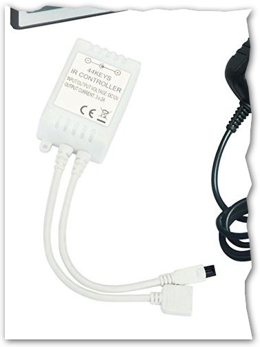
enter image description here

Figure 1. The IR controller.

The IR controller supplied with the kit interfaces the power and provides the data signal to the strip.

The simplest way to control from your micro is to fit it with an IR (infra-red) LED and transmit the codes to the IR controller. This method also makes it almost impossible for you to damage your micro or the LED strip as the only connection between them will be by infra-red light.

Someone has probably figured this out already and you may find the complete code for an Arduino in a web search.

6
  • 1
    Are you arguing that these are individually addressed and also have a distinct supply for each color? Not saying that is impossible, just that it seems odd. Typically I'd expect individually addressed LEDs to use a common supply, and those with distinct supplies to be only controllable per color, by current modulating the three power supplies. Commented Sep 25, 2016 at 18:26
  • I'm not arguing! ;^) Of course, you're right. I should probably have said "Your LEDs will require about 1000 mA or so per R, G and B colour." The advert is typically vague about the LED specs.
    – Transistor
    Commented Sep 25, 2016 at 18:37
  • I don't really think this is the simplest way ;p
    – aaa
    Commented Sep 25, 2016 at 20:44
  • @Paul actually re-using the existing drive box is simpler than engineering your own. Commented Sep 26, 2016 at 16:13
  • @Chris ah! I didn't check the link, but yeah, if that drivebox is included, it may be worth it. But i was thinking of "reverse engineering" the IR protocol and making your Arduino send it out. Adding a few mosfets to the RGB lines, and controlling them with analogWrite should be easier (in terms of coding). It just seemed like a work-around rather than a fix. (Though, with the IR receiver supplied, it makes sense)
    – aaa
    Commented Sep 26, 2016 at 16:34
0

No. there is no way to connect those directly.

You can use Solid state relays (SSR) for this. I did it before and was able to make different colors.

Connect an external 12v directly 12V pin in srips.

Use SSR to connect from GPIO to LED R G and B pins

1
  • They already include a driver, so that's not really true - you can inject remote signals into the driver, or directly drive its FETs. Commented Sep 26, 2016 at 16:11
-1

You can use a couple of relays on the arduino outputs, and control it from there.

3
  • Using MOSFET's, you can actually dim the R/G/B channels. (Mechanical) relays will wear out and are often too slow.
    – aaa
    Commented Sep 26, 2016 at 5:12
  • Please improve your answer giving specifics of how to solve the question asked.
    – sa_leinad
    Commented Sep 26, 2016 at 6:39
  • +1 There's no dimming requirement in the question, so this is a reasonable answer for on/off control. There really aren't specifics to give, beyond the connection details of whatever relay board is chosen. Commented Sep 26, 2016 at 16:13

Your Answer

By clicking “Post Your Answer”, you agree to our terms of service and acknowledge you have read our privacy policy.