6

so for about the last 8.5 hours (almost non-stop) I have been trying to figure out one issue and I have exhausted every search I could possibly think of.

I'm building a puzzle that requires 5 RFID readers on the 1 Arduino, but for the sake of testing i've only been using 2.

Both readers work independantly, I can read out the UIDs of the little cards, which is all I need to do, but as soon as I make them share the MISO line, it simply stops printing anything out. I have no idea why.

Both readers have a common external 3.3v power supply and ground, they share all other lines but have an individual Slave Select. For testing I put both of their MISO cables into a breadboard which then leads into the Arduino on PIN 12, but it will only print out the UID when only ONE cable is plugged into the breadboard.

So is there something special I need to do to make this work? Is there a reason why the readers sharing a MISO line would break it? Even if i don't initialise one of them, just for the fact that it's plugged in still breaks it. I have tried setting one to HIGH and one to LOW, both to LOW, both to HIGH, nothing changes it.

Also, something else kind of confusing to me, it's meant to be active LOW to activate the SS, but when only 1 is plugged into the MISO line, it doesn't seem to matter which state it's in, it always prints...

I did a little bit of testing on my sketch just a moment ago and realised that when both are plugged into the MISO, the sketch will not progress past this line (which is also the first line in the loop)

if ( ! mfrc522_2.PICC_IsNewCardPresent())
        return;

I know everything else is working because it works when there is nothing else plugged into the MISO line, but I need it to work when all the others are plugged in too.

Please please please, if you have any idea, let me know.

I'm using the MFRC522 Library

EDIT:

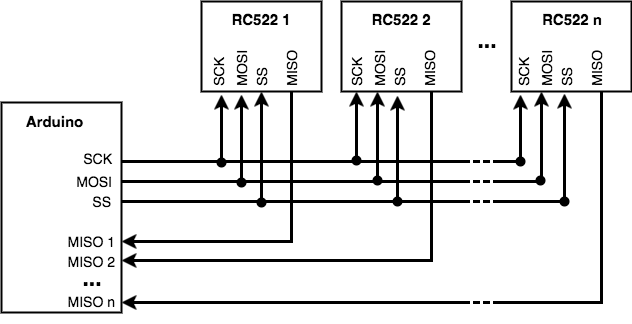
This is basically the setup i'm using: enter image description here

I'm not using any voltage translators or shifters, everything is 5v from the arduino except for the power to the readers which is coming from an external 3.3v supply like mentions previously.

I'm pretty certain that this is the datasheet for the RC522 i'm using, though i'm not sure if it's V1 or V2, but given the differences between them I don't think it matters:

http://www.nxp.com/documents/data_sheet/MFRC522.pdf

I don't know if they are able to share MISO lines like someone below said, I just assumed I could?

11
  • You are using a 5V arduino board without voltage translators, right? If so, you are out-of-specs for those modules, so this can make them malfunction
    – frarugi87
    Commented Dec 1, 2015 at 15:31
  • @frarugi87, that the readers work individually suggests that's not the problem. Also, MISO is an input to Arduino and 3V3-system outputs to 5V-system inputs are said to work ok. Commented Dec 1, 2015 at 18:26
  • Jesse Mount, please edit question and specify voltages used; whether voltage translators/shifters are used; and the model numbers of the readers. While SPI slaves typically use open-drain outputs so MISO can be wired together, some don't. Without a model number, who can say? Commented Dec 1, 2015 at 18:28
  • @jwpat7 Surely you mean tri-state outputs, not open-drain outputs...
    – Majenko
    Commented Dec 1, 2015 at 19:45
  • 1
    @jwpat7 Incidentally, I can find no mention of tri-state on MISO in the MFRC522 datasheet. Doesn't mean there isn't, but also doesn't mean there is...
    – Majenko
    Commented Dec 1, 2015 at 20:14

3 Answers 3

4

I am joining this conversation VERY late, however maybe my answer can help someone who is just now looking into this.

I was able to get SEVEN RC522 readers working on one Arduino! My solution was very similar to your idea, except instead of the SS pin, I used the MISO pin.

Unique MISO diagram

If you look into how the pins work, all of them are outputs going from the master (Arduino) to the slaves (RC522), EXCEPT for the MISO pin which is an input going from the slaves to the master.

So I gave each RC522 scanner it's own MISO pin on the Arduino, and the rest of the pins were shared with all the scanners.

To get it working with the code, the simplest solution I found was to initialize a new RFID using the corresponding MISO pin each time I wanted to read from one of the RC522s.

This worked for the Arduino because you can set several of the digital pins as MISOs, however I haven't figured out how to get this working on a Raspberry Pi yet (without using a multiplexer) because the Pi has a few specific pins that are used for MISO.

I was using the old Sunfounder library. At the bottom of this page (http://wiki.sunfounder.cc/index.php?title=Mifare_RC522_Module_RFID_Reader), if you download the "RFID-RC522_test_experiment" zip file it will have the library included. Just copy and paste the RFID1 folder into your Arduino Library folder. Here is a simple tutorial for that library: https://www.sunfounder.com/learn/RFID_kit_V1_for_Arduino/lesson-29-rfid-entrance-guard-system-rfid-kit-v1-0-for-arduino.html

Here is some example code. It is pretty ugly but it worked.

void checkRFID(int i){
  if(i==0){
    rfid.begin(2,4,5,7,3,6);
  }
  if(i==1){
    rfid.begin(2,4,5,8,3,6);
  }
  if(i==2){
    rfid.begin(2,4,5,9,3,6);
  }
  if(i==3){
    rfid.begin(2,4,5,10,3,6);
  }
  if(i==4){
    rfid.begin(2,4,5,11,3,6);
  }
  if(i==5){
    rfid.begin(2,4,5,12,3,6);
  }
  if(i==6){
    rfid.begin(2,4,5,13,3,6);
  }
  delay(100);
  rfid.init();
  uchar status;
  uchar str[MAX_LEN];
  // Search card, return card types
  status = rfid.request(PICC_REQIDL, str);
  if (status != MI_OK)
  {
    return;
  }
  // Show card type
  rfid.showCardType(str);
  //Prevent conflict, return the 4 bytes Serial number of the card
  status = rfid.anticoll(str);
  if (status == MI_OK)
  {
    memcpy(serNum, str, 5);
    rfid.showCardID(serNum);//show the card ID
    Serial.println();
    Serial.println();
  }
  delay(100);
  rfid.halt(); //command the card into sleep mode 
}
8
  • 1
    @sa_leinad I used normal Arduino Uno
    – Michael
    Commented May 10, 2017 at 1:14
  • 1
    @sa_leinad and I used sunfounder's libary. Here is their tutorial: sunfounder.com/learn/RFID_kit_V1_for_Arduino/… With their library you initialize the RFID by providing all the pins that should be used for each RC522 pin, like this: rfid.begin(irq,sck,mosi,miso,nss,rst); so it was as simple as changing the miso pin that i provided. So for example I would do rfid.begin(2,4,5,7,3,6); to check one reader, then do rfid.begin(2,4,5,8,3,6); to check the next reader, and so on.
    – Michael
    Commented May 10, 2017 at 1:26
  • 2
    Michael, you're awesome!!! I had problems to connect 5 rfid-modules for a week and nothing helped. You fixed my problem, thank you. It works perfectly :) Commented Aug 17, 2017 at 13:11
  • 1
    Hey man, you saved my time. Thank you. I just wonder why that library isn't in libraries or another places? Commented Dec 17, 2019 at 10:20
  • 1
    In fact, the "trick" don't really came from the RFID LIB from Sunfounder, but from the "sub librairy" they re using, which is in the same folder and which is.... SoftSPI! This lib seems to act a bit like Software serial as it allow you to declare the PINS you want for SPI. Very interesting!!!!
    – Peter
    Commented Apr 28, 2020 at 16:14
3

Looking at the datasheet for the MFR522, it is not clear that it even supports multidrop SPI. It does not mention anything about the state of the SPI output pins when the chip is not selected. It also mentions that the chip uses the slave select line to detect what communication mode to use upon startup, but does not mention anything about how the chip will react to changes on that pin after startup.

Considering this, along with the fact to your library also does not seem to support connections to multiple MFR522, my guess is that this chip only supports a 1-to-1 SPI link.

Further, the SPI Timing characteristics in the datasheet specify how lon gthe SS (called NSS) must be high before communication can begin, but does not specify how long after SS goes low that the MISO goes tri-state, which would be an important thing to know if the chip did support multidrop SPI.

This is all backed up by the behavior you are seeing. If both chips are driving the MISO line simultaneously, then communication will not be possible when both are connected.

To support multiple MFR522 connections, you could possibly...

  1. Use a multiplexing buffer to only enable SPI lines to one chip at a time. Downside is you would need Extra hardware, but upside is that you could probably use existing library intact by selecting the desired MFR522 before making the linrary calls.

  2. Connect each MFR522 to different GPIO pins on the Arduino and bit bang the SPI to each chip independently. Upside is that you don't need any extra hardware and you potentially have a lot of flexibility on how you access the MFR522's. Downside is you will have to retrofit this bit-banged SPI into the library or use (or write) a different library.

I've seen this question come up many times over the years, so if you do choose option #2, please publish your code so others can use it!

An Experiment

I'd propose you do this to find out if your chips are compatible with multi-drop SPI...

  1. Power up your system with a RC522 reader.
  2. Check and make sure it works.
  3. Disconnect the SS and MISO lines from the RC522 so they are no longer connected to the Arduino (or anything else). Leave the RC522 powered up - if it resets it might loose the auto-detected SPI configuration.
  4. Use a jumper to connect the SS line to ground.
  5. Connect the MISO line to ground with a 1K ohm resistor.
  6. Use a multimeter to check the voltage on the MISO line.
  7. Connect the MISO line to Vcc with the 1K ohm resistor.
  8. Use a multimeter to check the voltage on the MISO line.
  9. Connect the SS line to Vcc.
  10. Repeat steps 3-6.

Report back the table of the 4 voltage readings you got and we should have our answer!

5
  • While the data sheet could be clearer, It is extremely unlikely that a chip which claims to be an SPI peripheral will fail to ultimately tristate the MISO line when not selected. At any rate it should be easily tested. Commented Dec 2, 2015 at 3:08
  • I'd be inclined to agree, but a quick google search shows many people with the exact same problem - connecting a 2nd MFRC522 to the MISO line inhibits the 1st one from working. Also note that other NXP datasheets specifically mention tristate when available (ie the PCF85063BTL states that the SPI data out line is "is high-impedance when not driving". Without having a couple of the chips in hand to test there is no way to know for sure, but based on all the evidence I think most likely this chip does not support multidrop SPI.
    – bigjosh
    Commented Dec 2, 2015 at 3:40
  • If anyone has 2 of these in the NYC area, LMK and we can scope them up and get a final authoritative answer!
    – bigjosh
    Commented Dec 2, 2015 at 3:41
  • You don't need two of them to test that behavior - you can test it with one and a resistor. Commented Dec 2, 2015 at 7:02
  • "along with the fact to your library also does not seem to support connections to multiple MFR522" -- this doesn't seem to be true. It contains example code for using multiple readers: github.com/miguelbalboa/rfid/blob/master/examples/…
    – Jules
    Commented Jul 11, 2016 at 0:36
2

I do not know if every module has a pull-up resistance in sck and mosi if that is the case, it could be that for every module connected over teh lines the resistance gets lower. so maybe the module can not drop the voltage so there is no comunication. check with a multimeter the resistance between Vcc and MOSI it has to be around 4.7k generally. hope this could help.

Not the answer you're looking for? Browse other questions tagged or ask your own question.