2

I have an NRF24L01+ with the base module (regulates voltage) connected to an Arduino Uno 3. I'm using the tmrh20 NRF24 library and am running one of the example programs. I'm trying to sniff the SPI bus so I have a Saleae Logic 8 hooked up. As soon as I connect the clip to the MISO pin the Arduino program stops executing. I'm able to reproduce this 100% of the time. It seems it is only the MISO pin that is causing the problem. For the library I am using MISO uses pin 12 on the Uno 3.

Anybody know what is going on? It seems as if the Saleae is grounding pin 12 when I hook it up. Not sure why it is only pin 12 that is an issue though.

I can reproduce the same problem when I manually connecting pin 12 straight to GND as well.

I can collect samples without MISO just fine but that of course only tells me half the story.

Any suggestions?

EDIT: Here are some links and resources for more information.

I'm basically following the instructions from this article: http://arduino-info.wikispaces.com/Nrf24L01-2.4GHz-HowTo

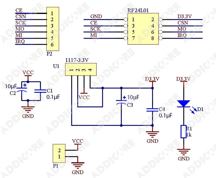
The breakout board http://www.addicore.com/1x-nRF24L01-Adapter-p/ad279.htm

And it's schematic: enter image description here

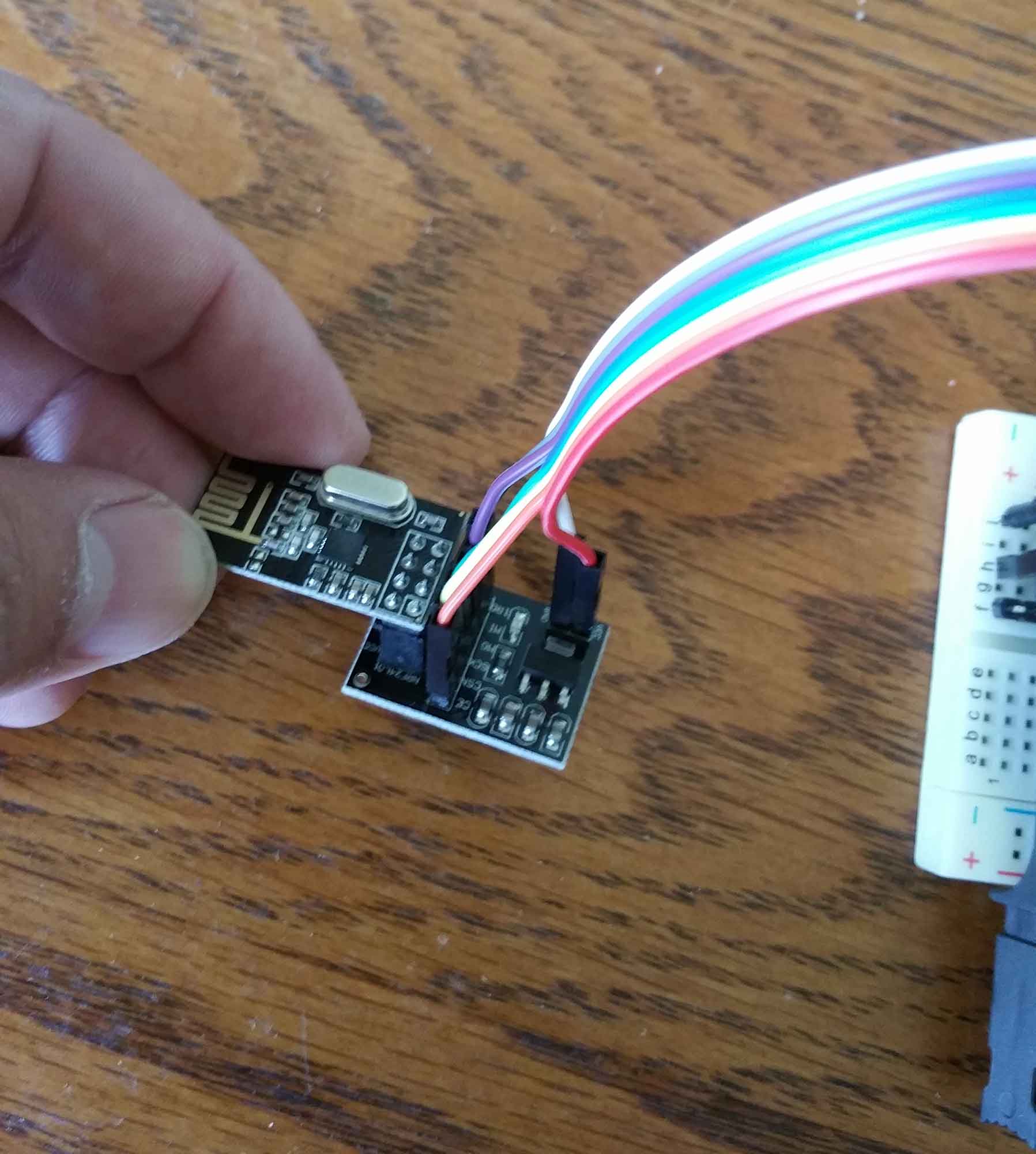
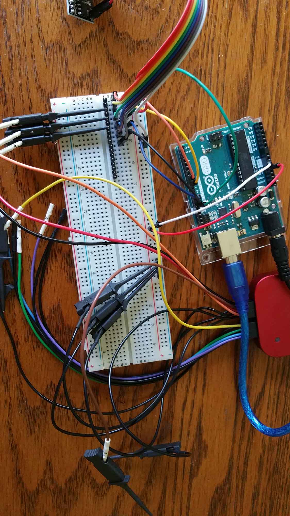
Link to the datasheet for the radio itself: http://www.nordicsemi.com/eng/Products/2.4GHz-RF/nRF24L01 enter image description here And some photos of how I have it wired up: enter image description here
4
  • Could you add a link to the NRF24L01+ module you are using and possible schematics? How do you connect ground to the Saleae Logic 8? Commented Sep 23, 2016 at 8:51
  • Added links. I connected a few of the ground pins on the Saleae to the ground rail on the breadboard (see photo above). The ground from the Arduino is connected to the ground rail on the breadboard. Commented Sep 23, 2016 at 17:47
  • 1
    Is the analyzer powered up? What does that channel read of it read? Try using a different channel of it. Also see what size resistor you can connect between the pin and ground without disturbing operation - 100K? 10K? 1K? Keep in mind your NRF24L01 will only be driving about 3.3v out, an ATmega at 5v has a relatively low Vih for a 5v part, but there won't be as much tolerance for loading as when using a 5v driver. Commented Sep 23, 2016 at 18:01
  • It seems to be a load issue from the logic analyzer. I added a pull up resistor between the 5V and the pin. I still have to have the resistor between the logic analyzer clip and the pin or else it will interfere with execution. What I see now is that the pin reads high 100% of the time when the clock is not going, and 100% of the time low when the clock is engage. I don't get any actual values for MISO (0x00 all the time). The high and low are easily within the logic threshold levels. I ordered some pots to fine tune the resistors to see if I can find a value that works. Suggestions? Commented Sep 27, 2016 at 20:36

1 Answer 1

1

It would appear from your description that the leads on your logic analyzer distort of the SPI MISO waveform and the Arduino does not read incoming data correctly.

To avoid this, you could place an digital isolator between the Arduino and the Logic 8.

Any decent oscilloscope should also allow you to read the SPI bus.

Your Answer

By clicking “Post Your Answer”, you agree to our terms of service and acknowledge you have read our privacy policy.

Not the answer you're looking for? Browse other questions tagged or ask your own question.