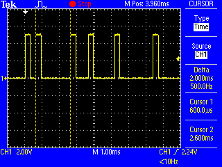
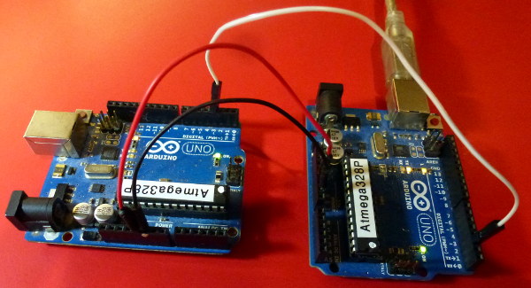
I tried to use a function that could smooth out the PPM by using 10 input values and finding the averages. But even this still doesn't seem to be a good way prevent the noise that is occurring when using my Remote. Is there any way to fix this? Here is the code from the smoothing project. (Although i feel it's not really necessary to add it here, but here it is anyways.)
My code is using the PPMrcIn library. An int is created and then using if statements I make an object do work. My problem is that i have a very small window for work.
My values are between 50 and 200
Where 140 is the preferred midpoint i'd like to work with.
This is my somewhat cryptic number line.
140 is in the middle. Where my window of stability is between 130 and 150
and values below 100 and above 180 are where the robot does some work.
50 ---x---<100-----130--<140>--150----180>---x---200
  /*

    Smoothing

    Reads repeatedly from an analog input, calculating a running average
    and printing it to the computer.  Keeps ten readings in an array and
    continually averages them.

    The circuit:
      * Analog sensor (potentiometer will do) attached to analog input 0

    Created 22 April 2007
    By David A. Mellis  <[email protected]>
    modified 9 Apr 2012
    by Tom Igoe
    http://www.arduino.cc/en/Tutorial/Smoothing

    This example code is in the public domain.


  */


  // Define the number of samples to keep track of.  The higher the number,
  // the more the readings will be smoothed, but the slower the output will
  // respond to the input.  Using a constant rather than a normal variable lets
  // use this value to determine the size of the readings array.
  const int numReadings = 10;

  int readings[numReadings];      // the readings from the analog input
  int index = 0;                  // the index of the current reading
  int total = 0;                  // the running total
  int average = 0;                // the average

  int inputPin = A0;

  void setup()
  {
    // initialize serial communication with computer:
    Serial.begin(9600);
    // initialize all the readings to 0:
    for (int thisReading = 0; thisReading < numReadings; thisReading++)
      readings[thisReading] = 0;
  }

  void loop() {
    // subtract the last reading:
    total= total - readings[index];
    // read from the sensor:
    readings[index] = analogRead(inputPin);
    // add the reading to the total:
    total= total + readings[index];
    // advance to the next position in the array:
    index = index + 1;

    // if we're at the end of the array...
    if (index >= numReadings)
      // ...wrap around to the beginning:
      index = 0;

    // calculate the average:
    average = total / numReadings;
    // send it to the computer as ASCII digits
    Serial.println(average);
    delay(1);        // delay in between reads for stability
  }
also link to my code in github https://github.com/tisaconundrum2/RCRoomba/blob/master/RCRoomba2.2.ino
Since this is being asked. Let me clarify on this black voodoo thing called a PPM.
Many RC Transmitters and Receivers provide access to the PPM Stream, this is a single stream of pulses which includes the information for all of the receiver channels in a single connection.
The stream is made up of a series of short pulses, the first pulse is the start marker. The time between the start marker and the start of the next pulse defines the pulse length for channel one. The time to the next pulse defines the pulse length for channel 2 and so on. The end of the pulse stream is marked by a gap know as the frame space. This gap indicates that there are no more channels to receive and the next pulse will be the start of a new frame. Each frame contains the pulse widths for all of your receiver channels.
Note - unlike servo signals, in a PPM Stream it is the gaps between pulses that defines the pulse width for a channel, not the duration of the pulse itself which can be very short.
-http://rcarduino.blogspot.com/2012/11/how-to-read-rc-receiver-ppm-stream.html
As discussed above. My PPM signal is highly varied. I want to be able to just get a solid 140. However, the signal will jump irratically between 135 and 142 for reasons I do not completely understand. In an attempt to clear this fuzziness I tried to go for smoothing.


I tried to use a function that could smooth out the PPM by using 10 input values and finding the averages.Could you clarify that somewhat? PPM - is that pulses per minute? Why would you want to smooth it out?a good way prevent the noise that is occurring when using my Remote- what remote?this still doesn't seem to be a good way prevent the noise that is occurring- what noise? Do you mean variations? Or actual noise that is completely different from what you are expecting?readings[index] = analogRead(inputPin);- why are you doing an analogRead? That's quite slow (104 µs). Why not digitalRead()? Personally if I was going for highly-accurate readings I would be using an interrupt to quickly note the time the next pulse arrives.delay in between reads for stability- delays here will add to your problems. I think the whole things needs a rework.