1

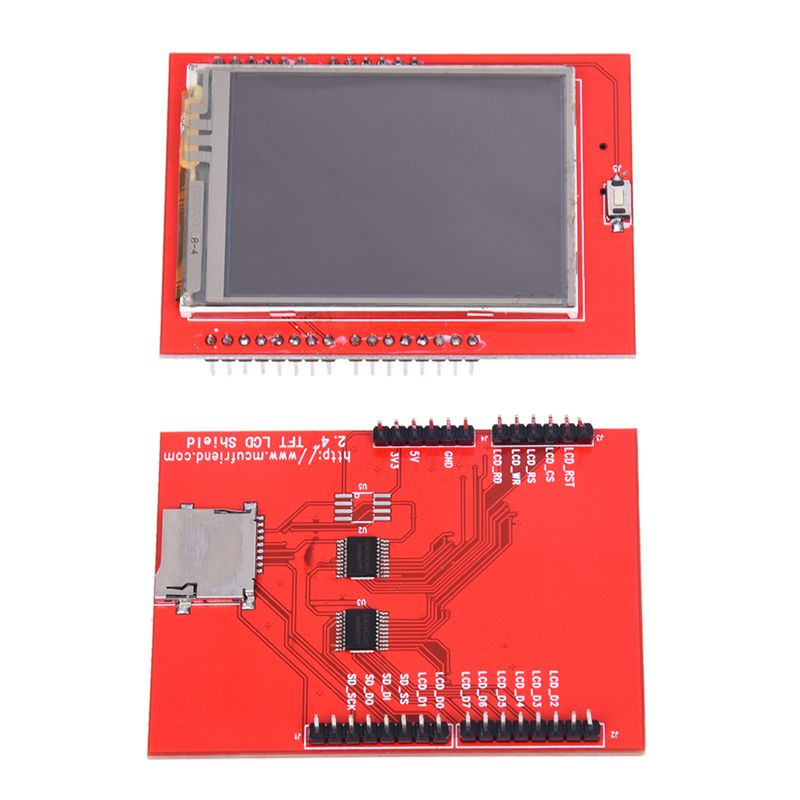
I have a Arduino Mega with LCD TFT 2.4"" with reading 5v signal on A8 pin (Arduino mega pin) from a raspberry pi (just to test). They are grounded together. When the Arduino is without the LCD, the analog reading works fine (4.8V,same from multimeter). But when I assembly the LCD, even if I just assembly VCC and ground, the analog read increasce around of 0.2V measure. I already tried to change the voltage input with a potentiometer and I still receiving a measure error of 0.2V. External energy supply to the LCD makes the things works, but I wouldn't like to have a external supply just to the screen.

What I'm doing wrong or what I can do ?

enter image description here

2
  • 1
    Measure the Arduino's 5V pin with the LCD attached. I'll bet it no longer measures 5V...
    – Majenko
    Commented Oct 5, 2021 at 9:34
  • Yeah, without the LCD attached i got a 4.95V. When I attach the LCD the Arduino's goes to 4.85V Commented Oct 5, 2021 at 14:01

2 Answers 2

1

MCUFriend went through a number of revisions of the same 2.4" TFT shield over time. I guess it depended on what TFT screens they could get hold of cheapest at any given moment. I have two versions here, neither of which are the same as yours. Both have their own voltage regulator onboard for the 3.3V power (which yours doesn't). Both of them also have resistors present on the cathode of the back light - which yours doesn't.

I would imagine for this revision they mistakenly though the TFT screen's back light didn't require any current limiting resistors and omitted them, with the end result that connecting the TFT screen to the Arduino drags down the 5V voltage to that of the combined forward voltage of the LEDs in the back light circuit.

In short: your TFT screen is designed badly. Fixing it would require modifying the shield on a trace-level basis. Not easy.

2
  • Yeah, It make sense. I was expecting that. Which lcd Tft do you recommend me ? Commented Oct 5, 2021 at 15:32
  • @GabrielLincoln They're all pretty much of a muchness. Look for one with a few more components on it than just some IO buffers. Personally I design and build my own direcly into products instead of using shields, but I do have a large collection here for when I was developing a big display library system. If you see a "resistor array" on the images of the TFT it's a pretty safe bet it's good.
    – Majenko
    Commented Oct 5, 2021 at 15:36
0
  • The short answer is to beef up your power supply:

Don't use small batteries or power supplies. For instance use D Size Cells instead of 9 Volt Cells. Or use a 3 Amp power supply instead of a 100mAmp power supply.

  • The longer answer:

Make sure you have mitigated any power problems. Like long or thin power lines. Long or thin wires have more resistance. And the more current you pull over that resistance the less voltage you will have at the far end. Remember it follows the rule:

Voltage = Resistance * Current

  • Probably the best answer:

Check the ADC specification of the processor and make sure your voltage reference is not adversely affected by power fluctuations. Some processors, like most used on Arduinos, have the ability to switch between internal references and external references. Most designers who really need a good ADC response will design an external reference and instruct the processor to use the external over the internal reference. For most Arduinos the function to call to switch references is "analogReference()". You can read more about this command and external references here.

Your Answer

By clicking “Post Your Answer”, you agree to our terms of service and acknowledge you have read our privacy policy.

Not the answer you're looking for? Browse other questions tagged or ask your own question.