2

I'm trying to follow lesson 6 of the Adafruit Arduino lessons on digital inputs found here.

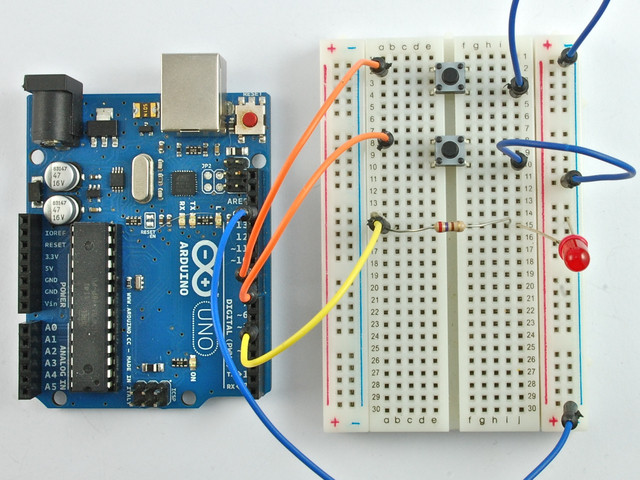
I have the same code and the board setup the exact same and the code it is working exactly as it should. I just can't figure out WHY.

Board:

enter image description here

Code:

    /*
Adafruit Arduino - Lesson 6. Inputs
*/

int ledPin = 5;
int buttonApin = 9;
int buttonBpin = 8;

byte leds = 0;

void setup() 
{
  pinMode(ledPin, OUTPUT);
  pinMode(buttonApin, INPUT_PULLUP);  
  pinMode(buttonBpin, INPUT_PULLUP);  
}

void loop() 
{
  if (digitalRead(buttonApin) == LOW)
  {
    digitalWrite(ledPin, HIGH);
  }
  if (digitalRead(buttonBpin) == LOW)
  {
    digitalWrite(ledPin, LOW);
  }
}

Why does the light turn on when one of he buttons is pressed once and turn off when the other button is pressed once. I don't understand the mechanism of how the press is being remembered.

There doesn't seem to be anything in the code that can explain why the button stays on even when no longer pressed, so it should be some component? But what?

Can anyone help explain why this is working?

3
  • 1
    you are falling into the trap of thinking this ... if the button is pressed and the light turns on, then the light must turn off if the button is released ... which part of the code tells the light to turn off when buttonApin is released?
    – jsotola
    Commented Aug 22, 2021 at 0:04
  • Look at the code carefully - If button A is low turn the led on and only if button B is low then will it turn off, so if you press button B it will turn off
    – Coder9390
    Commented Aug 22, 2021 at 12:34
  • The port manipulated by digitalWrite maintains a state, kind of like a variable.
    – timemage
    Commented Aug 22, 2021 at 13:35

4 Answers 4

2

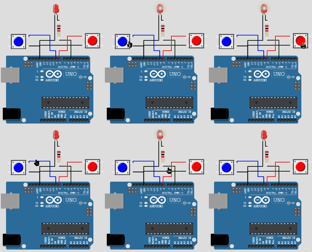
I would like to add two more cents. It is a wonderful explanation already from @chrisl Here is the simulation screenshot for your example:
enter image description here

if you consider mechanical switches, they really cut the connection so that the light will be OFF. When you want the light to be on, you will move the switch to the ON position(in this example, hold the button) enter image description here

In the case of Microcontrollers, and in the given example, it is more like two people communicating.

  1. The 1st person is looking at the switches. The 2nd person is controlling the LED
  2. 1st person is instructed to notify the second person about anybody pressing the switches
  3. whenever the ON switch is pressed, the 1st person will immediately tell the second person to turn on the LED
  4. Whenever the OFF switch is pressed, the 1st person will tell the 2nd person to turn off the LED

The behaviour of the program much depends on the requirement.


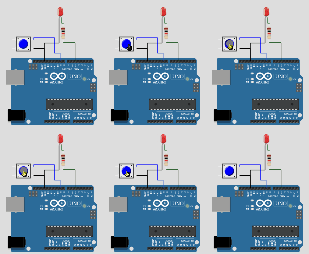
if you would love to see the LED turn OFF when you want to, you can try this example
enter image description here

Code:

/*
  Adafruit Arduino - Lesson 6. Inputs
*/

int ledPin = 5;
int buttonApin = 9;
//int buttonBpin = 8;

byte leds = 0;

void setup()
{
  Serial.begin(9600);
  pinMode(ledPin, OUTPUT);
  pinMode(buttonApin, INPUT_PULLUP);
  pinMode(buttonBpin, INPUT_PULLUP);
}

void loop()
{
  digitalWrite(ledPin, !digitalRead(buttonApin));
}
1

If you read the lesson below the first picture and above parts it states: "Pressing the button nearer the top of the breadboard will turn the LED on, pressing the other button will turn the LED off." Try pressing and expect the LED to turn off.

1

The press is not being remembered. Instead, the output pin "remembers" its state: digitalWrite(HIGH) sets the pin to high and the pin will remain high until you call digitalWrite(LOW).

1

It might be interesting to look at the reasons why the pin remembers its state (as described in other answers).

Every digital pin has dedicated digital output hardware, which can drive the pin to HIGH (Vcc, supply voltage) or LOW (ground). This output hardware is internally tied to a SFR (Special Function Register). A register is a piece of specific memory hardware in the microcontroller of the Arduino. The digital output hardware is electrically hardwired to some of those special function registers. Thus its state depends on what is saved in those registers. Since the registers hold their state during the running time of the Arduino (they are memory after all), the digital output hardware will also not change, until you change the corresponding registers (through executing digitalWrite()).

You can even manipulate the SFRs directly. This can help with programming time sensitive code or setting/reading multiple pins at once. All the digital pins are sorted into so called ports, which can hold up to 8 pins. For each port there are the following SFRs (the x stands for the character of the corresponding port, like PORTA, PORTB, ...), where the bits in these (1 byte big) registers correspond to one pin each:

  • DDRx: This register is the Data Direction Register. It controls if the corresponding pins are set as digital output or input.
  • PORTx: This register sets the output state. digitalWrite(pin, HIGH) will write a 1 to the corresponding bit of this register, which then sets the pin to HIGH. If the corresponding pin is set as input, setting a 1 in the corresponding bit of the PORT register will enable the interal pullup resistor of that pin.
  • PINx: This register holds the current state of the corresponding pins, so you can use it to read a digital pin.

You can also read this reference article. Also the datasheet of the used microcontroller also contains all information about what SFRs exist and how they are used to perform specific actions.

Your Answer

By clicking “Post Your Answer”, you agree to our terms of service and acknowledge you have read our privacy policy.

Not the answer you're looking for? Browse other questions tagged or ask your own question.