0

We have an Arduino Nano connected to 4 small (0.5") common-anode 7-segment displays and 2 large (3") common-anode 7-segment displays. We are trying to multiplex the displays. The larger one requires more power than the smaller one (9V) which the shift register cannot supply.

Therefore, we have supplied 9V to the open drain outputs of the shift register that are connected to the larger displays with a pull-up resistor (390ohm). However, more power (7.5V) goes to the resistor than the display (1.5V).

They are connected like in the ShiftDisplay library's schematic, with a pull-up resistor added according to this link on open drain.

How do we use the open drain outputs logic to supply power to the display?

The data sheet of the big 7-segment display can be found here. Each display requires 160mA of continuous current.

1
  • you should post a wiring diagram, your description is not sufficient. use the open drain outputs logic to supply power - you don't typically use pullup resistors to supply power to sth., maybe you confused that with urrent-limiting resistor?
    – Sim Son
    Commented Oct 14, 2020 at 21:07

2 Answers 2

1

You are getting confused. The pullup resistor is only needed on open drain when you are using it to generate logic levels. It turns the OD output into an RTL output.

You don't want that.

Instead you want your open drain outputs to act like a low-side switch transistor - which is infact what they are.

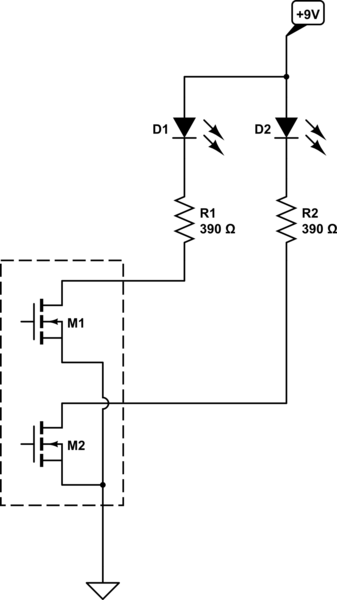
You can do that by simply placing your LEDs in series with your "pullup" resistor, thus:

schematic

simulate this circuit – Schematic created using CircuitLab

I have only shown two elements there (everything inside the dashed box is inside the shift register), but you can see now how when an output is "on" the transistor conducts, and the current flows through the LED, through the resistor, through the transistor, and down to ground.

Your resistor value is then calculated as simply

    9 - Vfled
R = ---------
      Iled

For 20mA and a 2V forward voltage that comes out as 350Ω - so your 390Ω resistors are perfectly fine.

2
  • Hi, I don't think this works for our specific 2-digit display (10 pin variant), your answer would require me to have one IC per display. Am trying to see how to use the open drain output on the anode side like in the miguelpynto GitHub. Commented Oct 10, 2020 at 8:39
  • It sounds like you have a multiplexed display. You don't want to use a shift register with one of those. You either need a multiplexing driver chip or to wire the display direct to the Arduino.
    – Majenko
    Commented Oct 10, 2020 at 8:47
0

Can you use different resistors for each display group? If so that will solve your problem along with what Majenko said.

Your Answer

By clicking “Post Your Answer”, you agree to our terms of service and acknowledge you have read our privacy policy.

Not the answer you're looking for? Browse other questions tagged or ask your own question.