0

this might be more general electronics question, forgive me if this is not the correct place to ask.

I am atempting to use the arduino and MCP4725 breakout board to inject 4 different voltages into an existing line that comes from V1.

V1 is the analog signal from an existing unit and varies between 2v, 3v and 4v. VM1 responds to those voltages and switches to a different working modes. 2v == Mode A, 3v == Mode B, 4v == Mode C.

My plan is to have MCP4725(represented as V2 below)hooked up to Arduino to simulate Modes A, B, C when needed.

MBR0540 D2 is there to prevent sending the voltage back to the sending unit, MBR0540 D1 is to do the same for DAC.

I am worried that if the D2 fails for whatever reason, I might loose the sending unit functionality.. is there a better way to do it?
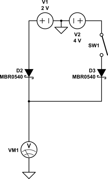
schematic

simulate this circuit – Schematic created using CircuitLab

Thanks for any help/comments you might have.

7
  • VM1 will receive the higher voltage of the two sources. If V1 is set to 4V then V2 will not be able to do anything - it will be ignored. Is that really what you want?
    – Majenko
    Commented Dec 22, 2019 at 15:29
  • yes, thats what I would like, to occasionally send higher voltage and change the Mode on the receiving end ignoring 2v in this case
    – amet
    Commented Dec 22, 2019 at 15:34
  • Here is a video about reverse voltage protection. It's my favorite one. High current is not your problem. But Afrotechmods shows more ;-). youtube.com/watch?v=IrB-FPcv1Dc . With the MOSFet solution you have nearly 0 voltage drop. Then you can make the protector more safe by using more stages. Commented Dec 22, 2019 at 15:58
  • You can also use two OpAmp Buffers en.wikipedia.org/wiki/Buffer_amplifier to separate the two outputs from each other. That has also the avantage of being able to drive more load, if you would need it. Commented Dec 22, 2019 at 16:04
  • There is also a solution I would like the most. As you ask for security, a complete separation of the two lines would be the best way. I would measure the output voltage of V1 with the arduino and if the arduino should overwrite it with a higher voltage it generates it with the MCP4725. Both outputs the V1 and V2 are connected to a 2 channel analog multiplexer. The arduino is able to toggle it for its needs. It depends on the security level you needs, whether you should use such a complicated solution. But I would do it, just for the fun ;-). Commented Dec 22, 2019 at 16:19

1 Answer 1

0

Unless you are really stressing it, it is highly unlikely that D2 would fail.

You could, though, replace both diodes with a simple SPDT switch to select between the two voltage sources.

Whatever you do, though, it probably has about the same chance (or more so) of failing (and the same end result) as having the diodes.

You could always add an "emergency override" switch that both bypasses D2 and isolates V2 in case of failure.

2
  • thanks for this, what would stress it? would giving it permanent 4v be considered stressing it?
    – amet
    Commented Dec 22, 2019 at 19:32
  • The MBR0540 supports up to 40V, so you're not even close to stressing it.
    – Holmez
    Commented Dec 22, 2019 at 22:49

Your Answer

By clicking “Post Your Answer”, you agree to our terms of service and acknowledge you have read our privacy policy.

Not the answer you're looking for? Browse other questions tagged or ask your own question.