2

I have built two parallel H-bridges from "Design 1" on this page as you can see in the attached schematic.

However when I apply the external power (VCC1 in the center of the diagram) the two motors do not spin.

Using my multimeter, I can see that the entire circuit is working: the motor is getting a 'forward' and 'backward' current as the Arduino sets the pins high. The multimeter is reading +/- 5.54V with the motor replaced by the multimeter. (Across the motor this drops to 0.13V)

So then I measure the current by putting my multimeter both in series with the motors and replacing the motors. There's only 40mA available! Looking around the web I found the suggestion to reduce the 220Ω resistors at R2, R3, R5 and R6. So I switched in (randomly) 27Ω resistors and the output current is still only 40mA.

What else should I try to bring up the current enough to drive the motors?

Edit: So my uneducated guess is that it's likely that the limitation is coming from the transistors. The Ns are BC549 and the Ps are BC559. The datasheets list "low current" as a feature, but I figured that was the collector.

Edit 2: The motor is this one which requires 70mA when running (and presumably more during startup)
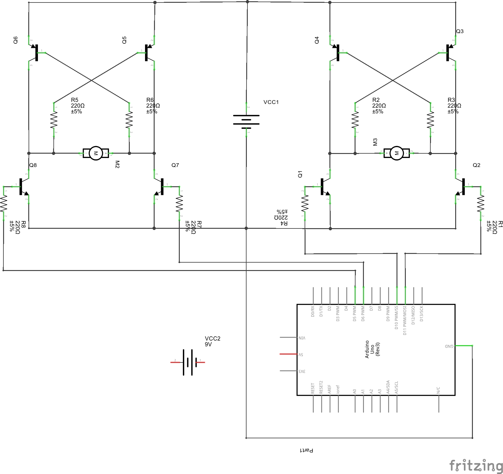
Schematic of two H-bridges controlled by Arduino

Edit 3: Code driving the Arduino:

// Pin setup
int pinLeftMotorFwd   = 5;
int pinLeftMotorBck   = 6;
int pinRightMotorFwd  = 10;
int pinRightMotorBck  = 11;

// Directions for the {left, right} motors to achieve the four directions
int FORWARD[]   = {  1,  1 };
int BACKWARD[]  = { -1, -1 };
int RIGHT[]     = { -1,  1 };
int LEFT[]      = {  1, -1 };


void setup() {
    Serial.begin(9600);

    pinMode(pinLeftMotorFwd,  OUTPUT);
    pinMode(pinLeftMotorBck,  OUTPUT);
    pinMode(pinRightMotorFwd, OUTPUT);
    pinMode(pinRightMotorBck, OUTPUT);
}

void loop() {
    go( FORWARD, 10 );
    go( RIGHT,    3 );
    go( FORWARD, 10 );
    go( LEFT,     6 );  
}

// Move the bot in a particular direction from the array above for a given number of seconds
void go ( int dir[], int dur ){
    leftMotor(  dir[0] );
    rightMotor( dir[1] ); 
    delay( dur * 1000 );
}

// Sill both motors (OK, so stop both motors. But stop is a keyword in C)
void still(){
    leftMotor(  0 );
    rightMotor( 0 );
}

// Set the left motor to Backward (-1), Forward (1), or Stop (0)
void leftMotor( int dir ){
    // Pull both pins low
    digitalWrite(pinLeftMotorFwd, LOW );
    Serial.println("pinLeftMotorFwd LOW");
    digitalWrite(pinLeftMotorBck, LOW );
    Serial.println("pinLeftMotorBck LOW");

    // If we're going forward, pull the Fwd pin high
    if( dir == 1 ){
        digitalWrite(pinLeftMotorFwd, HIGH);
        Serial.println("pinLeftMotorFwd HIGH");
    }

    // otherwise, pull the Bck pin high
    else if( dir == -1 ) {
        digitalWrite(pinLeftMotorBck, HIGH);
        Serial.println("pinLeftMotorBck HIGH");
    }
}  

// Set the right motor to Backward (-1), Forward (1), or Stop (0)
void rightMotor( int dir ){
    // Pull both pins low
    digitalWrite(pinRightMotorFwd, LOW );
    Serial.println("pinRightMotorFwd LOW");
    digitalWrite(pinRightMotorBck, LOW );
    Serial.println("pinRightMotorBck LOW");

    // If we're going forward, pull the Fwd pin high
    if( dir == 1 ){
        digitalWrite(pinRightMotorFwd, HIGH);
        Serial.println("pinRightMotorFwd HIGH");
    }

    // otherwise, pull the Bck pin high
    else if( dir == -1 ) {
        digitalWrite(pinRightMotorBck, HIGH);
        Serial.println("pinRightMotorBck HIGH");
    }
}  
3
  • 1
    Design 1 would not have been my first choice. Commented Dec 28, 2014 at 7:09
  • What is the VCC1's power source. Is it a battery? By the way, 220 Ohm is pretty low value. That will result in 22mA of current (at 5v) going into the base. With a gain of 270 that would result in a collector current of around 6A. I'd try using increasing the resistors to 1 kOhm to 5 kOhm.
    – Gerben
    Commented Dec 28, 2014 at 18:53
  • @Gerben: Ahh .. I see I may have messed up. I reduced the resistance. I'll try increasing it before I switch to a different circuit per Mark Williams below Commented Dec 29, 2014 at 1:39

1 Answer 1

1

Design 1 wouldn't be my first thought on how to do this either! The transistors aren't a great choice, but are cheap & common.

The layout here is more conventional, and you can physically link 1-2, & 3-4 to connect to your arduino without the risk of short circuits.

I suspect your code may be setting both lines high together - the only advantage I can see to the posted circuit is that this does not necessarily cause smoke (but may well do as you describe). This is why posting the code is recommended!

4
  • Thanks for the suggestion. The transistors were on-hand. Ultimately once I understand the concepts from "first principles" / discrete components, then I'd just replace the whole lot with either a motor driver circuit or a dedicated H-bridge. The table at the bottom of the circuit you suggest indicates I need to switch pins between VCC/GND/Disconnected. How can linking 1-2 attached to a pin and 3-4 attached to another pin give me full control? (Code isn't setting both high, but I'll attach it anyway) Commented Dec 28, 2014 at 22:43
  • 1
    The point of the H-Bridge is that the transistors work in pairs - so you would have 1&2 or 3&4 on together, but never 1&3 or 2&4 - if you go back to 'Design 1' you will observe that a single input has been put through an inverter stage to ensure this doesn't happen - your re-design replaces that with software - OK 'til a bug sets up a short.. So with the standard arrangement on that link, the truth table at the bottom (disregard the not-connected options) shows you the combinations. You have off/brake/forward/backward and possibly PWM as well.. Commented Dec 28, 2014 at 23:51
  • No diodes at home, so I built it on circuit.io: 123d.circuits.io/circuits/511807-h-bridge where I had the exact same problem as my original circuit. Until I realised the NPNs were in backwards. Then everything came good. Going to check my original circuit tomorrow and see if I did the same there before I rebuild. Commented Jan 2, 2015 at 11:28
  • Turns out my actual problem was having the transistors around the wrong way. I couldn't get my circuit to work so I built yours and got exactly the same thing. The above circuits.io result gave me a clue so I played with them and got them around the right way. Turns out that the side that appears flat in Fritzing is the round side and vice-versa. Commented Jan 13, 2015 at 11:42

Your Answer

By clicking “Post Your Answer”, you agree to our terms of service and acknowledge you have read our privacy policy.

Not the answer you're looking for? Browse other questions tagged or ask your own question.