0

I am not sure an Arduino forum is the right place to ask this question, but since I'm using Arduino here I thought it would be a good starting point. I am trying to connect a lever (you can think of it as a switch, when it's pressed it's ON, and otherwise it's OFF) to an Arduino via a USB connector. My setup worked perfectly fine when I connected the lever directly to the Arduino, but via the USB it doesn't work. Since I already built and invested in USB connectors I would like to solve this issue, or at least understand what I am doing wrong in here.

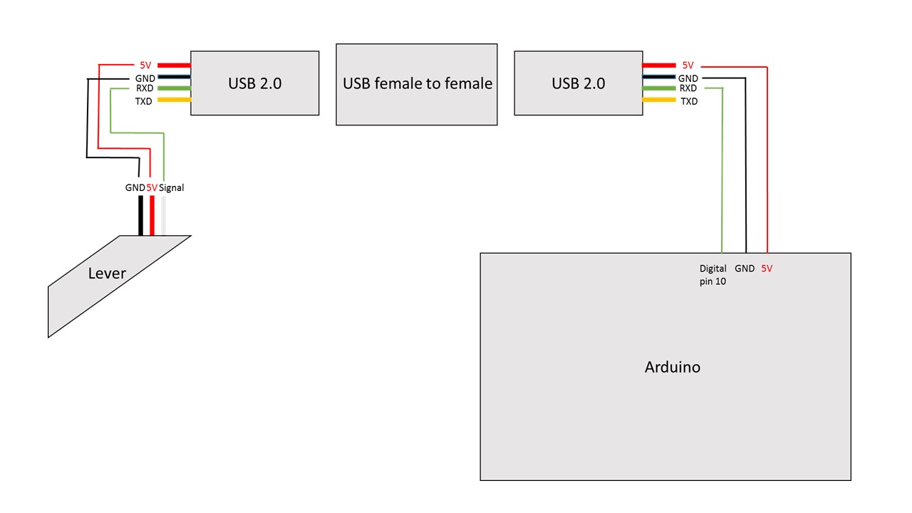
I've attached a photo to demonstrate the wiring. Note that it works if I bypass this USB connection. I'm trying to understand why this doesn't work via a USB. enter image description here
6
  • to clarify, you're using a USB connector, but not for a USB connection? perfectly valid thing to do, just check if the female to female doesn't "cross" the grn/yellow connections Commented Jul 19, 2016 at 3:08
  • 1
    As there is not really a legitimate role for USB female to female cables, any you find should be considered highly suspect. It is quite possible they do not connect all of the pins through, or do not connect them in the way you believe they should be connected. And generally speaking, using USB connectors for a different purpose is a bad idea - it is just asking for confusion. Commented Jul 19, 2016 at 4:32
  • Thank you both. Yes, I'm using a USB connector, but not for a USB connection. I guess the problem is indeed the female to female connector. I agree this was a bad idea, but I'm already invested in this solution as I made 16 Arduino boards following this schematic. I can re-wire everything and try different connectors, but it would be great if I could make this work without spending more money on different connectors. Commented Jul 19, 2016 at 5:43
  • @ChrisStratton I have a female to female USB A cable here. It has a perfectly legitimate role. It came with my oscilloscope and is used for connecting the USB A socket on the front to a USB A socket on a PC. The oscope then switches its OTG to Device mode and the PC sees it.
    – Majenko
    Commented Jul 19, 2016 at 8:59
  • 1
    That is not a legitimate use in the eyes of the USB spec, hence the cable was not supposed to exist. I've had needs like that too, and sourcing a solution can be hard - when you are shopping for something that isn't supposed to exist, you run into vendors that sell creative fiction. A working cable certainly can be made, but it's not necessarily what you will get when you buy. Commented Jul 19, 2016 at 12:35

1 Answer 1

3

I'd suggest using a multimeter to figure out what's connected to what after hooking up the complete wiring scheme; there aren't that many options and you should be able to figure out what's connected to what soon enough. On a more philosophical note, it's only a bad idea if the alternatives weren't worse.

1
  • I support this answer. If you use a multimeter you can test which pins of the USB connection are linked. I've used USB cables in the past for several installations as well, i.e. for sound or to control NeoPixels. It works quite good, but you have to make sure all the things are wired properly.
    – Len
    Commented Jul 19, 2016 at 11:39

Your Answer

By clicking “Post Your Answer”, you agree to our terms of service and acknowledge you have read our privacy policy.

Not the answer you're looking for? Browse other questions tagged or ask your own question.