3

Here's the deal, I'm attempting to learn how to use an FFT (Fast Fourier Transformation) Library for sound analysis (link is here). My issue is that this comes with included C++ code to show users how to use the FFT library. There are three examples, but I'll show this one because it's closest to the application I have planned for it:

/*
fft_adc_serial.pde
guest openmusiclabs.com 7.7.14
example sketch for testing the fft library.
it takes in data on ADC0 (Analog0) and processes them
with the fft. the data is sent out over the serial
port at 115.2kb.
*/

#define LOG_OUT 1 // use the log output function
#define FFT_N 256 // set to 256 point fft

#include <FFT.h> // include the library

void setup() {
  Serial.begin(115200); // use the serial port
  TIMSK0 = 0; // turn off timer0 for lower jitter
  ADCSRA = 0xe5; // set the adc to free running mode
  ADMUX = 0x40; // use adc0
  DIDR0 = 0x01; // turn off the digital input for adc0
}

void loop() {
  while(1) { // reduces jitter
    cli();  // UDRE interrupt slows this way down on arduino1.0
    for (int i = 0 ; i < 512 ; i += 2) { // save 256 samples
      while(!(ADCSRA & 0x10)); // wait for adc to be ready
      ADCSRA = 0xf5; // restart adc
      byte m = ADCL; // fetch adc data
      byte j = ADCH;
      int k = (j << 8) | m; // form into an int
      k -= 0x0200; // form into a signed int
      k <<= 6; // form into a 16b signed int
      fft_input[i] = k; // put real data into even bins
      fft_input[i+1] = 0; // set odd bins to 0
     }
    fft_window(); // window the data for better frequency response
    fft_reorder(); // reorder the data before doing the fft
    fft_run(); // process the data in the fft
    fft_mag_log(); // take the output of the fft
    sei();
    Serial.println("start");
    for (byte i = 0 ; i < FFT_N/2 ; i++) { 
      Serial.println(fft_log_out[i]); // send out the data
    }
  }
}

Now, with that said, I have a very general grasp of the idea that those lines referencing some variable called ADMUX and ADCSRA have to do with the analogRead() method and that the ADCH and ADCL refer to another two components that are combined to provide the returned integer that analogRead() spits out. What I don't understand whatsoever are those seemingly random strings of characters that these are being set equal to. For example, what does 0x40 or 0x01 or 0xe5 even refer to in the setup() method (if nothing else maybe somebody could point me in the right direction for this, because that part I really am entirely clueless about). And furthermore, why manipulate these directly in the first place, because if you reference the source code for analogRead() they look awfully similar. Thanks for any help in advance!

3
  • All is explained in Chap. 24 atmel.com/images/…, Commented Feb 10, 2016 at 23:33
  • The register-level manipulations are trying to optimize the sampling rate to be faster than you get out of analogRead() sampling rate.
    – Dave X
    Commented Feb 11, 2016 at 3:56
  • The random values in ADMUX differ, depending on the chip, but it can choose the pin, internal sensors, reference voltage, etc... What they really mean depends on the datasheet.
    – Dave X
    Commented Feb 11, 2016 at 4:13

2 Answers 2

1

It would have been preferable if the author of that code had used proper bit masks. For example:

  ADCSRA = 0xe5; // set the adc to free running mode

Looking at the datasheet:

ADCSRA

Now, 0xe5 is 11100101 in binary.

So that line could have been written:

  ADCSRA = bit (ADEN) | bit (ADSC) | bit (ADATE) | bit (ADPS2) | bit (ADPS0);

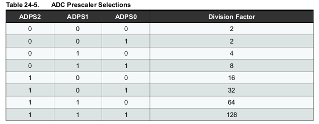
The last two (ADPS2 and ADPS0) give the prescaler (of 32):

ADC prescaler

The other bits are explained in the datasheet:

  • Bit 7 – ADEN: ADC Enable

    Writing this bit to one enables the ADC. By writing it to zero, the ADC is turned off. Turning the ADC off while a conversion is in progress, will terminate this conversion.

  • Bit 6 – ADSC: ADC Start Conversion

    In Single Conversion mode, write this bit to one to start each conversion. In Free Running mode, write this bit to one to start the first conversion. The first conversion after ADSC has been written after the ADC has been enabled, or if ADSC is written at the same time as the ADC is enabled, will take 25 ADC clock cycles instead of the normal 13. This first conversion performs initialization of the ADC. ADSC will read as one as long as a conversion is in progress. When the conversion is complete, it returns to zero. Writing zero to this bit has no effect.

  • Bit 5 – ADATE: ADC Auto Trigger Enable

    When this bit is written to one, Auto Triggering of the ADC is enabled. The ADC will start a conversion on a positive edge of the selected trigger signal. The trigger source is selected by setting the ADC Trigger Select bits, ADTS in ADCSRB.


You can work through the other registers in a similar way.

1

Nick Gammon already gave a very fine answer about the meaning of the mysterious numbers you were wondering about. Here I am trying to answer only your last question:

why manipulate these directly in the first place, because if you reference the source code for analogRead() they look awfully similar.

One of the reasons is, as Dave X said in a comment, to get a higher sample rate. Assuming this is an Arduino Uno or similar (ATmega328P @ 16 MHz), the Arduino core normally configures the ADC prescaler to 128. This gives a conversion time of 104 µs (equal to 13 × prescaler ÷ F_CPU), and a maximum sample rate of about 9.6 kHz. This is fine for telephone quality audio, but insufficient for hi-fi applications. This example code sets the prescaler to 32 for a conversion time of 26 µs and a maximum sample rate around 38 kHz. According to Atmel, the ADC should work fine with this kind of sample rate, except that you should not expect to get the full resolution.

The main reason, however, is not to get a fast sample rate, but rather to get a consistent sample rate. The problem with analogRead() is that it is a blocking function. If you look at its source code you will see a busy wait like this:

// ADSC is cleared when the conversion finishes
while (bit_is_set(ADCSRA, ADSC));

This means that the CPU is not doing anything useful while waiting for the ADC to finish the conversion. If you do analogRead() in a loop, the CPU will wait for the ADC, then the ADC will be idle while the CPU completes the loop and so on. The conversion period is then the time required by the ADC plus the time taken by the CPU to loop. And the CPU time is hard to predict because it can be influenced by interrupts and by conditional branches inside the loop.

This code, in contrast, configures the ADC to work in free running mode. In this mode, the ADC starts a new conversion as soon as the previous one is done. This way you get a steady sample rate while the ADC and the CPU work in parallel. In the loop you see these lines:

while(!(ADCSRA & 0x10)); // wait for adc to be ready
ADCSRA = 0xf5; // restart adc

The comments are a bit misleading. The first line (which I would rather write loop_until_bit_is_set(ADCSRA, ADIF);) waits for a flags that is set when the current conversion is done and the data register updated. The next line does not restart the ADC (it restarted itself, as it is in free running mode): it only clears the flag so that it can be meaningfully tested on the next iteration.

Now, I have a few comments on this code that are not directly related to your question, but may be useful if you are going to build your program on this basis.

First, it should be noticed that the whole ADC-reading loop is done with interrupts disabled. This is not normally needed, as the free running mode gives you a steady sampling even if the CPU timing is somewhat jittery. The only valid reason I see for disabling interrupts is if one of your ISRs takes so long to execute that you may miss one sample. This could very well be the case with such a high sampling frequency. But still, there is no point in keeping the interrupts disabled during the FFT processing. And there is no point in turning off Timer 0 if you are disabling interrupts anyway.

My second point is about the three lines starting with byte m = ADCL;. Those are meant to read the ADC data register in the proper order: low byte first. However, the C compiler is well aware of the proper way to do read a 16-bit I/O register (see “Accessing 16-bit Registers” in the datasheet chapter about Timer 1). Thus, these three lines can be simplified to just int k = ADC;.

My last point is that having the CPU left adjust the result (k <<= 6) takes some time, as it is implemented as a loop. There is no point in doing this when the ADC can do it for free: you just have to set the ADLAR bit when configuring ADMUX in setup(). Then the 5 lines starting with byte m = ADCL; would be reduced to

int k = ADC - 0x8000;  // ADC reading as a 16 bit signed int
1
  • An excellent answer from Edgar Bonet. My reply described how to interpret the bit patterns. This reply goes into a lot more detail about the meaning of them.
    – Nick Gammon
    Commented Feb 11, 2016 at 19:40

Your Answer

By clicking “Post Your Answer”, you agree to our terms of service and acknowledge you have read our privacy policy.

Not the answer you're looking for? Browse other questions tagged or ask your own question.