5

I want to build a scheme to get data from several DS18B20 sensors and write their temperature to serial. Before I connected them using parasite mode and using 2,7k resistor (because I didn't have 4,7k at home). Back then, it worked for 1 device, if I plug in another, it won't detect any of them (it writes "No more addresses"). Now I replaced 2,7k resistor with 4,7k and it doesn't detect any device connected. But if I do one little thing, which is replacing 4,7k resistor back with 2,7k, it will detect one device.

How to fix it?

Here is exactly how it is all connected now: enter image description here
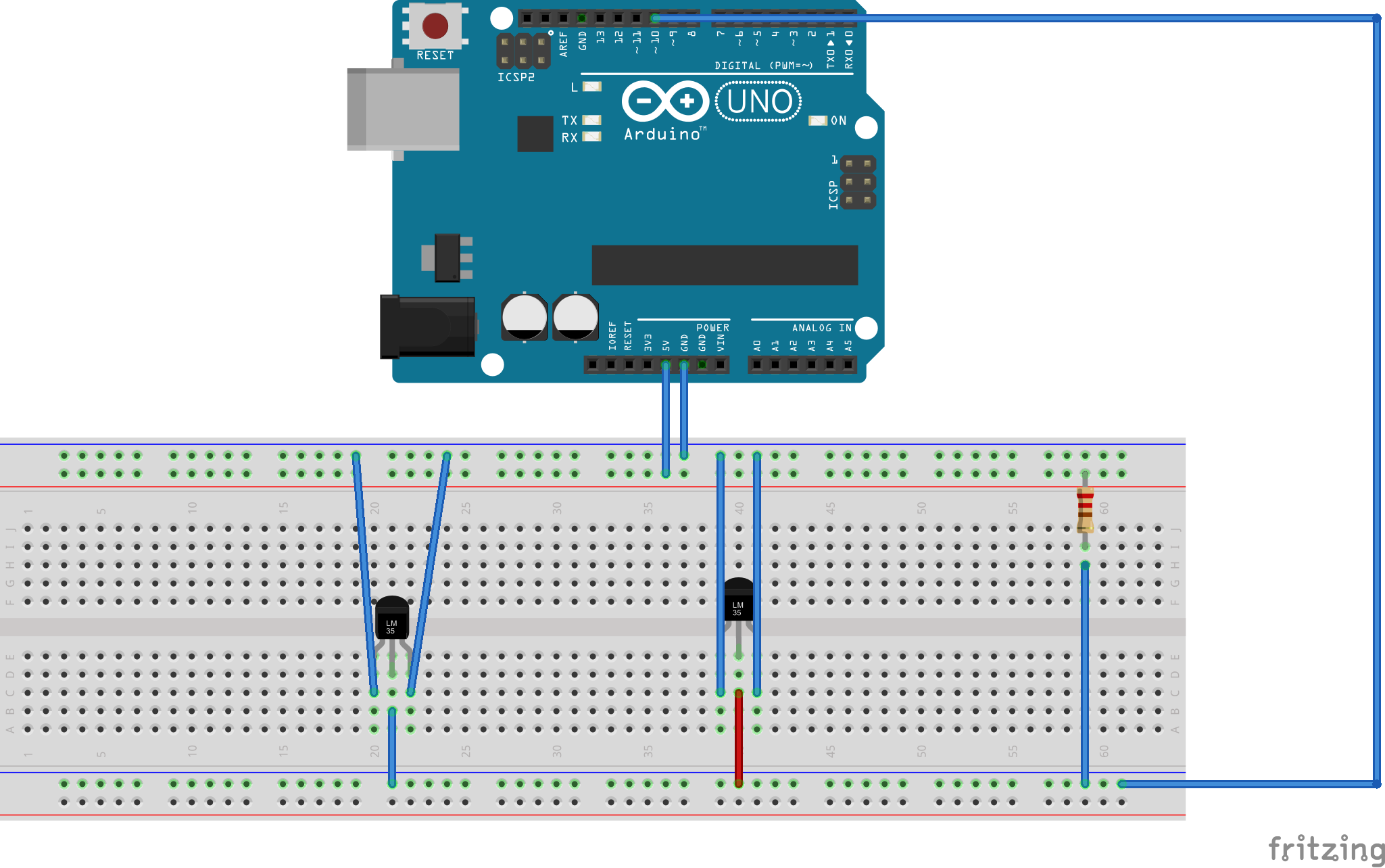
and here is the default sketch I am using:

#include <OneWire.h>

// OneWire DS18S20, DS18B20, DS1822 Temperature Example
//
// http://www.pjrc.com/teensy/td_libs_OneWire.html
//
// The DallasTemperature library can do all this work for you!
// http://milesburton.com/Dallas_Temperature_Control_Library

OneWire  ds(10);  // on pin 2 (a 4.7K resistor is necessary)

void setup(void) {
  Serial.begin(9600);
}

void loop(void) {
  byte i;
  byte present = 0;
  byte type_s;
  byte data[12];
  byte addr[8];
  float celsius, fahrenheit;

  if ( !ds.search(addr)) {
    Serial.println("No more addresses.");
    Serial.println();
    ds.reset_search();
    delay(250);
    return;
  }

  Serial.print("ROM =");
  for ( i = 0; i < 8; i++) {
    Serial.write(' ');
    Serial.print(addr[i], HEX);
  }

  if (OneWire::crc8(addr, 7) != addr[7]) {
    Serial.println("CRC is not valid!");
    return;
  }
  Serial.println();

  // the first ROM byte indicates which chip
  switch (addr[0]) {
    case 0x10:
      Serial.println("  Chip = DS18S20");  // or old DS1820
      type_s = 1;
      break;
    case 0x28:
      Serial.println("  Chip = DS18B20");
      type_s = 0;
      break;
    case 0x22:
      Serial.println("  Chip = DS1822");
      type_s = 0;
      break;
    default:
      Serial.println("Device is not a DS18x20 family device.");
      return;
  }

  ds.reset();
  ds.select(addr);
  ds.write(0x44);        // start conversion, use ds.write(0x44,1) with parasite power on at the end

  delay(1000);     // maybe 750ms is enough, maybe not
  // we might do a ds.depower() here, but the reset will take care of it.

  present = ds.reset();
  ds.select(addr);
  ds.write(0xBE);         // Read Scratchpad

  Serial.print("  Data = ");
  Serial.print(present, HEX);
  Serial.print(" ");
  for ( i = 0; i < 9; i++) {           // we need 9 bytes
    data[i] = ds.read();
    Serial.print(data[i], HEX);
    Serial.print(" ");
  }
  Serial.print(" CRC=");
  Serial.print(OneWire::crc8(data, 8), HEX);
  Serial.println();

  // Convert the data to actual temperature
  // because the result is a 16 bit signed integer, it should
  // be stored to an "int16_t" type, which is always 16 bits
  // even when compiled on a 32 bit processor.
  int16_t raw = (data[1] << 8) | data[0];
  if (type_s) {
    raw = raw << 3; // 9 bit resolution default
    if (data[7] == 0x10) {
      // "count remain" gives full 12 bit resolution
      raw = (raw & 0xFFF0) + 12 - data[6];
    }
  } else {
    byte cfg = (data[4] & 0x60);
    // at lower res, the low bits are undefined, so let's zero them
    if (cfg == 0x00) raw = raw & ~7;  // 9 bit resolution, 93.75 ms
    else if (cfg == 0x20) raw = raw & ~3; // 10 bit res, 187.5 ms
    else if (cfg == 0x40) raw = raw & ~1; // 11 bit res, 375 ms
    //// default is 12 bit resolution, 750 ms conversion time
  }
  celsius = (float)raw / 16.0;
  fahrenheit = celsius * 1.8 + 32.0;
  Serial.print("  Temperature = ");
  Serial.print(celsius);
  Serial.print(" Celsius, ");
  Serial.print(fahrenheit);
  Serial.println(" Fahrenheit");
}

Is there anything I am doing wrong? Because I somehow managed to get it working some time ago.

5
  • 1
    Wow, switching the resistor to 620R worked. Guess I have a problem within my breadboard. Commented Dec 17, 2015 at 15:10
  • 1
    Have you tried without parasite power, or you have any particular reason for using parasite power?
    – brtiberio
    Commented Dec 17, 2015 at 15:14
  • 1
    Breadboard create a bit of capacitance on the data line. Try placing the second module right under first (so sharing the same breadboard "columns").
    – Gerben
    Commented Dec 17, 2015 at 15:40
  • @Personagem it was just easier to connect, in my opinion. Is there any difference? Commented Dec 17, 2015 at 16:10
  • Some sources advise to not use with multiple devices ( openenergymonitor.org/emon/buildingblocks/…). However data sheet says it is possible as long a strong pullup is present. I would go with the normal power with 4.7k pullup. Be very carefull connecting vdd to correct PIN in sensor. It will burn in seconds if you reverse polarity.
    – brtiberio
    Commented Dec 17, 2015 at 16:24

2 Answers 2

1

A problem with what you are doing on the breadboard is that you show no bypass capacitors.

What makes the pull up "strong" is the ability to provide current to move the data line from zero back to one. The load on the data line is its capacitance. To move the data line from 0 to 1, you have to charge that capacitor. Working on a bread board, you are correct that you have a larger capacitive load. So you require more current to move the data line from zero to one quickly.

You are correct that the lower 620 ohm resistor will provide more current. The large current will move the capacitance load of the data line more quickly. But you are not paying attention to the other side of the resistor, the 5V rail.

The layout you have has inductance in the wires from the Arduino power supply out to the bread board. An inductor has a voltage drop across it proportional to the rate of change of the current through it:

V = L  di/dt

The analogy is that inductance is a flywheel: if it is not spinning, it will take force to get is moving. Similar, once it is spinning, it will take force to stop it.

So when the resistor starts conducting to pull up the data line, the inductance in the wires and breadboard cause a voltage drop. The +5 side of the resistor voltage drops. This inductance in the wires leading to the resistor prevents it from rapidly charging the data line back to 1.

That is the role of bypass capacitors. You place 1 or 2 right at the resistor between the +5 and GND strips on the bread board. Now when the resistor draws current, it initially pulls from the energy stored in the capacitors. After a short time, the current will start pulling from the +5 wire. Thereby, you have bypassed the inductance of the +5 supply, hence the name.

Add a 0.1 microFarad ceramic capacitor on your breadboard where the wires connect to the contact strips. You will see this on schematics for anything that has a DC supply off board. Right next to the power connector will be 2 or 3 capacitors, usually one big 2-10 uF tantalum and one smaller 0.1 uF or so. Similar across circuit boards you see bypass caps placed at the supply voltage pin of every chip, commonly two: a 0.1 uF and a smaller 10 nF.

It might seem pointless to place a small capacitor in parallel with a larger capacitor. The values just add, yes? But again, the time response is different. Capacitors are not perfect and have internal series resistance. A big 10 uF electrolytic capacitor may store a lot of energy, but it is not fast in terms of how quickly it can start providing current. A little 100 nF ceramic monolithic capacitor is very fast, but doesn't have much energy.

So with two bypass caps in parallel, you have the small one for the initial burst of current, the larger cap for the heavy lifting, and last and slowest the 5V wires and traces to supply to steady current.

1
  • 0.1uF == 100nF. Commented Dec 19, 2015 at 11:52
0

A strong-pullup seems to be the key to having multiple sensors in parasitic mode, as described in the datasheet for the DS18b20 devices. Though they suggest using a MOSFET to pull up the 1-wire bus, I've had good results (3 meters of wire, 3 devices more than 2 meters out) by tying an output port directly to the 1-wire bus, bypassing the 4.7K resistor.

// One wire bus strong-pullup:
//
//    +------------+     +5v            +---------+     +---------+
//    |    MCU     |      |             | DS18b20 |     | DS18b20 |
//    |            |  R_pu = 4.7K       | g  d +5 |     | g  d +5 |
//    | Strong-    |      |             +-o--o--o-+     +-o--o--o-+
//    | Pullup   > o------o               |  |  |         |  |  |
//    |            |      |               +--|--+         +--|--+
//    |            |      |               |  |            |  |
//    |    Data <> o------o---------------|--o------------|--o------ - - -
//    |            |                      |               |
//    +------------+                      V               V

Initialize the strong-pullup port by setting the port as an output and HIGH, the disable and enable it by changing the port mode, not the output value. (Setting the port mode to input floats it, rather than grounding it as setting it LOW would do. This technique was suggested to me by Dave Tweed in Electrical Engineering Stack Exchange.)

Your Answer

By clicking “Post Your Answer”, you agree to our terms of service and acknowledge you have read our privacy policy.

Not the answer you're looking for? Browse other questions tagged or ask your own question.