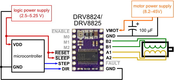
I'm using the Pololu DRV8825 Stepper Motor Driver to control a NEMA 17 Steppermotor with an Arduino Uno. According to the Pololu website, the circuit should be wired as follows:

I did, however, deviate from this exact sketch a little bit:
- The Arduino (microcontroller) is powered by a USB cable connected to the computer
- I connected the 5V pin on the arduino to the + rail on a breadboard. I then connected two wires on this rail to the RESET and SLEEP pins on the driver.
- I'm using a 9V battery to power the motor.
- I've connected the DIR and STEP pins to Arduino Uno pins 12 & 13, respectively.
Consequently, I coded and uploaded the following sketch:
int stp = 13;  //connect pin 13 to step
int dir = 12;  // connect pin 12 to dir
int a = 0;     //  gen counter

void setup()
{
  pinMode(stp, OUTPUT);
  pinMode(dir, OUTPUT);
}

void loop()
{
  if (a <  200)  //sweep 200 step in dir 1
   {
    a++;
    digitalWrite(stp, HIGH);
    delay(10);
    digitalWrite(stp, LOW);
    delay(10);
   }
  else
   {
    digitalWrite(dir, HIGH);
    a++;
    digitalWrite(stp, HIGH);
    delay(10);
    digitalWrite(stp, LOW);
    delay(10);

    if (a>400)    //sweep 200 in dir 2
     {
      a = 0;
      digitalWrite(dir, LOW);
     }
    }
}
RESULT
The stepper motor does not turn. Instead, it just hisses at a high pitch. After a short while, the driver gets very hot.
THINGS I'VE TRIED
- I double checked to make sure that connected stepper wires pairs are properly connected to the "A" pins and "B" pins on the driver.
- I tried reversing the A1-A2 pair and B1-B2 pair in all possible combinations. All combinations produce the same result as above.
- I tried increasing the motor power supply to 12V (8 alkaline AA batteries). The same result occurs.
- I double checked to make sure the 100microF radial electrolytic capacitor is connected with the long end to the positive motor supply and short end to the negative motor supply (on a different breadboard rail than the logic power supply, of course).
- I tried using the 3.3V pin instead of the 5V pin to connect to SLEEP and RESET on the driver. Again, the same result occurs.
I'm not really sure what to try next to debug my circuit.
My Hunch:
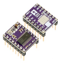
I do, however, have one suspicion based on a little warning box on the pololu website which reads:
Caution: Installing the header pins so that the silkscreen side is up and the components are down can limit the range of motion of the trimpot used to set the current limit. If you plan on installing the header pins in this orientation, please set the current limit before soldering in the pins.
The way I soldered the headers onto the driver looks like the bottom left corner of the picture below:

My Question:
Given that my stepper motor requires 1.7A current, is there anything I can do to improve this circuit to make it work? Did I make any mistakes? Is there anything else I should try or check? Did I solder the header in the wrong way?

digitalWrite(stp, HIGH);and low? that's clocking it. I think it wants you to leave it high.