8

I'm using the Pololu DRV8825 Stepper Motor Driver to control a NEMA 17 Steppermotor with an Arduino Uno. According to the Pololu website, the circuit should be wired as follows:
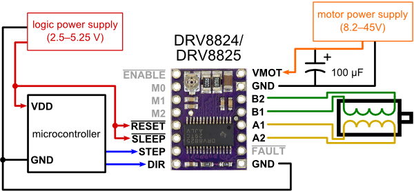
enter image description here

I did, however, deviate from this exact sketch a little bit:

  1. The Arduino (microcontroller) is powered by a USB cable connected to the computer
  2. I connected the 5V pin on the arduino to the + rail on a breadboard. I then connected two wires on this rail to the RESET and SLEEP pins on the driver.
  3. I'm using a 9V battery to power the motor.
  4. I've connected the DIR and STEP pins to Arduino Uno pins 12 & 13, respectively.

Consequently, I coded and uploaded the following sketch:

int stp = 13;  //connect pin 13 to step
int dir = 12;  // connect pin 12 to dir
int a = 0;     //  gen counter

void setup() 
{                
  pinMode(stp, OUTPUT);
  pinMode(dir, OUTPUT);       
}

void loop() 
{
  if (a <  200)  //sweep 200 step in dir 1
   {
    a++;
    digitalWrite(stp, HIGH);   
    delay(10);               
    digitalWrite(stp, LOW);  
    delay(10);              
   }
  else 
   {
    digitalWrite(dir, HIGH);
    a++;
    digitalWrite(stp, HIGH);  
    delay(10);               
    digitalWrite(stp, LOW);  
    delay(10);

    if (a>400)    //sweep 200 in dir 2
     {
      a = 0;
      digitalWrite(dir, LOW);
     }
    }
}

RESULT
The stepper motor does not turn. Instead, it just hisses at a high pitch. After a short while, the driver gets very hot.

THINGS I'VE TRIED

  1. I double checked to make sure that connected stepper wires pairs are properly connected to the "A" pins and "B" pins on the driver.
  2. I tried reversing the A1-A2 pair and B1-B2 pair in all possible combinations. All combinations produce the same result as above.
  3. I tried increasing the motor power supply to 12V (8 alkaline AA batteries). The same result occurs.
  4. I double checked to make sure the 100microF radial electrolytic capacitor is connected with the long end to the positive motor supply and short end to the negative motor supply (on a different breadboard rail than the logic power supply, of course).
  5. I tried using the 3.3V pin instead of the 5V pin to connect to SLEEP and RESET on the driver. Again, the same result occurs.

I'm not really sure what to try next to debug my circuit.

My Hunch:

I do, however, have one suspicion based on a little warning box on the pololu website which reads:

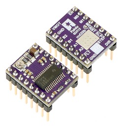
Caution: Installing the header pins so that the silkscreen side is up and the components are down can limit the range of motion of the trimpot used to set the current limit. If you plan on installing the header pins in this orientation, please set the current limit before soldering in the pins.

The way I soldered the headers onto the driver looks like the bottom left corner of the picture below:
enter image description here

My Question:
Given that my stepper motor requires 1.7A current, is there anything I can do to improve this circuit to make it work? Did I make any mistakes? Is there anything else I should try or check? Did I solder the header in the wrong way?

11
  • 2
    The direction of the pins shouldn't matter.. it's just saying it may be hard to turn the trimpot with the black plastic part of the headers right up against it so it recommends doing it the way you did it.
    – sachleen
    Commented May 3, 2014 at 20:58
  • @sachleen I presume the trimpot is that tiny circular part that looks like a screw. Do I need to turn it to adjust the current draw? If so, how can I tell exactly how much current I'm actually getting?
    – Paul
    Commented May 3, 2014 at 21:31
  • Yeah it's the circular thing in the top-left of the bottom image (component side up). Not sure if you need to change it. Read the "Current limiting" section of the pololu.com to see how to see what kind of current its drawing.
    – sachleen
    Commented May 3, 2014 at 21:58
  • @sachleen: Ok. I see. It says "to measure the current running through a single motor coil without clocking the STEP input". But I'm not sure what "without clocking the STEP input" means... Do you understand what that means?
    – Paul
    Commented May 3, 2014 at 22:13
  • 2
    I've never used a stepper so I might have no idea what I'm talking about. buuut... See where you do digitalWrite(stp, HIGH); and low? that's clocking it. I think it wants you to leave it high.
    – sachleen
    Commented May 3, 2014 at 22:17

4 Answers 4

6

I had this same issue when setting up this circuit with this code and driver on an Arduino Uno. All else was fine, but the current for the motor was set WAY too high on the driver from the factory. The VREF was 1.7 volts, and it needed to be around .5 for the motor I was using. As I set the VREF to the appropriate voltage, the motor started to spin as it should and stopped hissing.

I know this post is old, but I hope that this helps someone else. Pololu has a great video (and documentation in general) for setting the appropriate voltage on most of their drivers on the product page here: DRV8825 Stepper Motor Driver Carrier, High Current.

2

A couple things I noticed first: This is one of the best formatted questions I've ever seen... :) Anyway, your circuit looks fine to me except for a few things:

Warning: This carrier board uses low-ESR ceramic capacitors, which makes it susceptible to destructive LC voltage spikes, especially when using power leads longer than a few inches. Under the right conditions, these spikes can exceed the 45 V maximum voltage rating for the DRV8825 and permanently damage the board, even when the motor supply voltage is as low as 12 V. One way to protect the driver from such spikes is to put a large (at least 47 µF) electrolytic capacitor across motor power (VMOT) and ground somewhere close to the board.

(Added some italic/bold myself, quote from product page.)

Capacitors are cheap ($1.50 on eBay from US), and although new drivers are too, it's generally a good idea to build it right. There's nothing more annoying than waiting for shipping on something you shouldn't have had to fix.

Additionally, battery power (especially AAs) can be bulky if not done right, and may not provide enough current. Note that in a series configuration that it will provide the voltage of 8 AAs, but only the current of one. You can't run a 1.7 A motor off of a single AA's current. Stab in the dark guess: you'll need ~80-100 AAs to provide enough current and voltage. I'm too lazy to measure the internal resistance and actually calculate it.

Suggested solution: There are a million things that could go wrong. Without being there, I'm betting that your delay function is too short. What this will do is not provide enough time for the motor to move, thus it staying still. This would still use a lot of current (50% of the time it's full current to motor coils), therefore it would make the driver hot. (Note on heat: ...to supply more than approximately 1.5 A per coil, a heat sink or other cooling method is required... -Product page: you'll need a heatsink to cool your chip down.) Also note that some heat is normal; a general rule of thumb is if it's too hot to hold your thumb on it for a few seconds, you need more cooling. Remember that the more it's used, the hotter it'll get, so keep this in mind when deciding if you want to add a heatsink.

tl;dr: You need to increase the delay time and provide more current than you have currently.

12
  • I just tried increasing the delay time to 1000ms (1 second), and still no change in behavior. I guess I'll have to try batteries that can provide higher amperage. I looked up my AA batteries and found that they provide about 900 milliamp-hours. Should I look for batteries that provide at least 1700 milliamp-hours (corresponding to the 1.7amp current draw from the stepper motor)?
    – Paul
    Commented May 4, 2014 at 1:10
  • @Paul No, this is a common misconception. A mAH means that it has the capacity to release that much power, not that it can release that all at once. Since it's hard to tell the maximum current on most one-time batteries, I'd recommend getting a 9.6V rechargeable "RC battery" that can provide 1.8+A (amps, not amp hours). They can get a bit costly, but you need that much power. Advice: don't try adding rechargeable batteries in series. They're highly dangerous if not perfectly "balanced!" Commented May 4, 2014 at 1:59
  • Please stop giving mistaken advice about batteries. Most cells can supply a current many times their mAh rating, by a factor of 10 or more (the C rating). "Balance" is largely a charging concern, and primarily with lithium chemistries - something neither a 9.6v RC pack nor individual 1.2 - 1.5v AA cells utilize. Commented May 4, 2014 at 4:43
  • There is already a 100uF cap shown on the circuit, so why mentioneing that adding a cap is needed?
    – jfpoilpret
    Commented May 4, 2014 at 6:51
  • @Chris By balanced I meant that if you combine two slightly different lithium batteries they can be highly dangerous. From what I can tell, the OP is using standard AA alkaline batteries which I am positive that one can't support two amps at a time. Even if it could, it most likely wont last twenty minutes because of voltage loss in the battery. There is no chip to manage voltage loss. The OP hasn't specified the battery composition they are using, either, so it may be able to supply enough current, if charged enough. Commented May 4, 2014 at 12:56
2

I don't think your batteries were too low in current capacity, your delay time is not too short, at 10 +10 ms per clock pulse, you are only talking about 50 steps per second, that's not all that fast. I've written programs where I have had to go to microseconds to get enough rpm out of my stepper.

First, take everything out of your loop except the digitalwrite high, delay digitalwrite low and delay lines. Then the program "should" just spin the motor continuously in one direction. That way you are sure you don't have a logic issue. Second, did you check to see if you didn't hook up pin 12 and 13 backwards, such that you are telling the driver to change direction every 10 ms instead of stepping? The sound it makes would be more like a buzz or vibration, usually a soft, staticy hiss is when the motor is enabled, but not getting a step pulse.

Finally, this post is about 18 months old, it is considerate and helpful to others to explain how you solved the problem (assuming you figured it out).

1

The one thing that helped me was NOT to connect GND to stepper board from microcontroller (bottom black line from schematic posted in first post).

If it was connected, driver would draw 12V@3A immediately and gets freaky hot. Also motor didn´t turn at all.

1
  • No, you are mistaken. A common ground is absolutely necessary for this to function, and if you are not getting one there you are probably getting one through the AC wiring. Whatever cause your overheating was a different issue. What you have posted here is bad advice. Commented Jan 3, 2016 at 16:42

Your Answer

By clicking “Post Your Answer”, you agree to our terms of service and acknowledge you have read our privacy policy.

Not the answer you're looking for? Browse other questions tagged or ask your own question.