4

I need to make voltage divider, so I could read a battery voltage up to 14.4 V. Could I use very high resistance resistors for that, so the current would be very low (to not to discharge battery)?

On the Internet there are examples with 500 - 2000 ohm resistors, but could I use hundreds of thousands to reduce the current to minimum? Would Arduino's analog input still read the value?

2
  • I think I've seen power management IO, that could measure current, voltage and provide its readings through I2C line. So it might be the correct way how to do it. INA3221?
    – KIIV
    Commented Oct 21, 2020 at 8:43
  • This sounds like a project that isn't going to do what you think it is. Are you trying to build a battery tester? To tell you if your tool batteries are still good?
    – J...
    Commented Oct 22, 2020 at 13:26

6 Answers 6

11

The most efficient is not to have a voltage divider at all. Or at least to only have a voltage divider when you actually need one.

My preferred schematic is this:
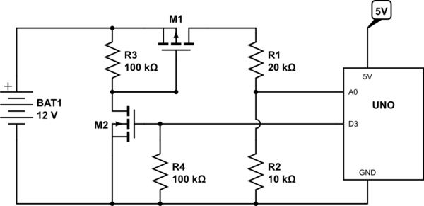
schematic

simulate this circuit – Schematic created using CircuitLab

With this M1 is normally kept turned off by R3. When you want to take a measurement you turn on M2 by setting D3 HIGH (or whatever pin you attached it to) which pulls down the gate of M1 turning it on. This then connects the batter to the voltage divider R1/R2 and allows you to read the voltage at A0.

The voltage divider of 20k / 10k allows you to read up to 15V on the battery, and gives you an output impedance of 6.67kΩ which is within the recommended maximum of 10kΩ for the ATMega's ADC.

During "idle" times when M1 and M2 are both off the only current flowing is the minuscule leakage current through M2 tempered by the large 100kΩ resistor R3 (which itself pales into insignificance compared to the "off" resistance of M2 anyway).

Selecting M1 so that the ON resistance is very small (<0.1Ω) allows you to essentially ignore it in your calculations since that will be swamped by the tolerance of R1 and R2 anyway. M2 needs to be selected so that it is "logic level" (i.e, with a gate threshold V_GS well below 5V).

This double-FET arrangement should be used rather than just using an N-channel FET in the ground connection of the divider because when that simpler arrangement is turned off the Arduino will be seeing 12V directly connected to A0 which really is not good - you will kill the Arduino - so it is important that you switch the "high" side of the network not the "low" side, and to do that requires two FETs.

2
  • 2
    What are some jellybean FETs for this purpose? Commented Oct 21, 2020 at 22:24
  • 2
    @PeterMortensen I'd probably use the BSS138P (n channel) and the IRLML5203 (p channel) in a sot-23 footprint.
    – Majenko
    Commented Oct 21, 2020 at 22:38
3

Yes, you can use very high value resistors for your voltage divider. But the recommended maximum is 10 kohms for the ADC pins. So the combined resistance of your two resistors should be maximum 10 kohms.

it is recommended that whatever you connect to the A/D have an output impedance of 10k or less for best accuracy. This is to allow the A/D input capacitor on the sample and hold to charge up in the time allotted to it between switching the input multiplexer over and starting the conversion.

From: Input Impedance of A0-A5

2
  • 5
    Note that calculating output impedance is not as simple as adding the resistors together. The resistors are actually calculated in parallel not series, so two 20k resistors would give 10k output impedance.
    – Majenko
    Commented Oct 21, 2020 at 10:13
  • 1
    There are more details in another source. Commented Oct 21, 2020 at 22:16
1

I was able to implement it with 3 MΩ resistors. The problem is that the readanalog() function executes 10 reads. So the first one is the right value and then you will not measure the right value anymore.

Solution: A voltage divider with 2.5 MΩ and 500 kΩ with a 470 nF capacitor on the 500 kΩ resistor. The solution with the MOSFET is better. This is easier, and it works (but only for 20 years 😜).

0

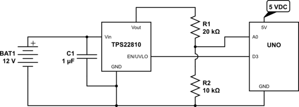
This is a variation on Majenko's design above. It was such a good idea, I couldn't resist submitting this - a reduced-component-count version:

schematic

simulate this circuit – Schematic created using CircuitLab

The TPS22810 is a load switch that enables or disables Vout (2.7V ≤ Vin ≤ 18V; Iout ≤ 3A). The output is determined by the EN/UVLO input that may be driven by a 1.8 V, 3.3 V or 5 V GPIO output. This component and the C1 bypass cap replaces 2 FETs and 2 Resistors. The TPS22810 cost is $0.50 ea. in small quantities.

The TPS22810 will likely find its most useful application as a high-side switch, but it seems to serve the purpose of the OP's need for driving a voltage divider also.

0

Everybody is missing the point here. The lower limit on the series resistance of the voltage divider is the self-discharge rate of the battery. For instance, a Li-ion battery loses about 10% of its charge per month. For a 3000 mAH 18650 cell, that's about 300 mAH per month, meaning about 300/(30X24) = 0.42mA constant drain. So, for a 8V stack made of 2 18650 cells in series, we get a total series resistance of 8V/0.42 of about 19K-ohms. IOW, if I put a 19K resistor across an 8V stack, I would get about the same battery drain as the battery would see if I left it completely alone. As long as the series resistance is much greater than that, it won't affect the battery life at all. So, if I use 2ea 50K resistors for a total series resistance of 100K, it will have very little effect on battery life. 2ea 50K resistors will present an effective output impedance of about 25K to the ADC input port on a MCU, and that is low enough so there will be little or no distortion of the measured voltage, and any offset can be easily compensated out in software. Moreover, if you want to go to a higher division ratio (say 4:1 instead of 2:1) the effective output resistance goes DOWN because it's a parallel circuit from the ADC's POV, but still a series circuit from the battery's POV. If I use a 75/25K divider for a 4:1 ratio, the parallel output impedance is 18.75K.

So, no need for fancy switching circuits - just choose a series divider with a convenient ratio and with a total series resistance in the 100K range, and you are done.

-2

I don't see any problem with reasonably high resistors (however see below). You are right that they would discharge the battery less.

Would Arduino's analog input still read the value?

Of course, if there was a voltage there to read. Why wouldn't it? A really high resistance might let the reading be affected by stray voltages.

A possible work-around would be to only take the reading occasionally, say, every 10 seconds. You could do this by making the reading be between a couple of Arduino pins, and leave one "floating" until you are ready to read it.

However that is not a good idea for reading a 12V battery. You need the voltage divider to be "active" so you don't have 12V on the Arduino input pin. Majenko's suggestion sounds better in that respect.

I have a lengthy discussion about the ADC on the Atmega328P. Reply #5 on that page discusses how it takes its measurements. This is done by charging a "sample and hold" capacitor. With too high an input impedance the capacitor would charge too slowly, and thus the subsequent sampling would give incorrect readings. A source signal impedance of 10k is recommended in the datasheet, so a voltage divider along those lines would be appropriate.

Majenko's suggestion of 20k + 10k would only involve a 0.4 mA constant current flow through the voltage divider, which for a 12V battery is probably not a huge deal (even without all that switching circuitry).

6
  • 2
    What is the actual (DC) input impedance? Commented Oct 21, 2020 at 22:10
  • 1
    The input impedance is 100 MΩ, but there are other considerations. Commented Oct 21, 2020 at 22:21
  • 1
    One reason it might not be able to read the voltage is that the Auduino's analog input will put a load on the voltage divider. Assuming the Auduino's input acts like a resister connected to ground (which is only an assumption for purposes of argument), then it will be connected in parallel with the 'bottom' resister of the voltage divider. This will alter the resistance and cause the Auduino to read a lower voltage than expected.
    – David42
    Commented Oct 22, 2020 at 14:02
  • @David42 That's right. In fact I have a lengthy discussion about that (too lengthy to post here) on my page about the ADC in the Atmega328P. I'll edit that link into my answer.
    – Nick Gammon
    Commented Oct 22, 2020 at 20:49
  • @NickGammon Reading at your answer and post about ADC, it seems to me that the simple solution proposed by Adriano should work great. That was to add a capacitor in parallel with the resistor connected to ground. What would be the problem of that? Commented Jul 30, 2023 at 21:51

Your Answer

By clicking “Post Your Answer”, you agree to our terms of service and acknowledge you have read our privacy policy.

Not the answer you're looking for? Browse other questions tagged or ask your own question.