Commonmark migration
Source Link

###TL;DR - Can the six yellow ISP pins be used as a normal ISP?

TL;DR - Can the six yellow ISP pins be used as a normal ISP?


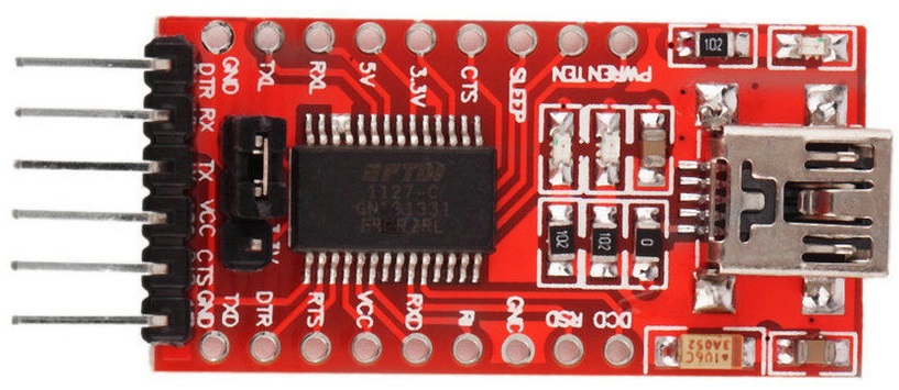
The usual USB-TTL FTDI breakout board looks like this:

USB-TTL FTDI Breakout board

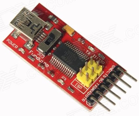
Recently, I came across a variant of the board shown below. However, what are the additional yellow header pins on this board for? They are labelled ISP.

USB-TTL FTDI Breakout board with ISP

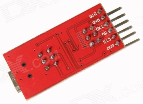
Here is a view of the rear:

USB-TTL FTDI Breakout board with ISP rear

So can they really be used as a standard ISP/ICSP?

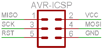
AVR-ICSP

However, according to the diagram below, which labels the 6 pins in question, I am not sure that there is a valid correlation of signal lines.

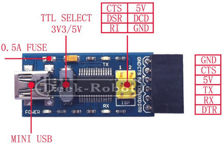
USB-TTL FTDI Breakout board with ISP with legend

That is to say, would CTS to MISO, RI to RST, DSR to SCK and DCD to MOSI work? Or is that why a special version of avrdude is required, as alluded to in FT232RL: USB to Serial 232 TTL Adapter –?and ISP? - post #6:

As a new feature there is a 6-pin ISP header available. With it, avrdude and avrftdi you can program Atmels and Arduino bootloaders. A special version of avrdude with compiled FTDI driver is neccessary.

However the provided link to that version of avrdude, with the compiled FTDI driver, is dead.

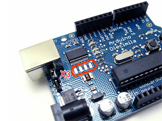
It is also said, in post #7, that these pins are actually equivalent to an X3 connector, as found on the older Arduino Dicimila/NG/Duemilanove boards.

X3 header on Diecimila

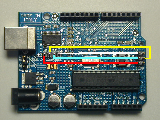
and those can (evidently) be used like so, as a bit banged SPI,

Connecting X3 header to ISP header on Diecimila

It should be noted that the RI, CTS, DCD and DSR (labelled RSD) pins are available, along the sides of the original FTDI breakout board. So, does the breakout board with the ISP header just provide access to these same signals using a different header?

I am a little confused - have I just over thought this, and this breakout board is simply an ISP/ICSP header and an FTDI connector rolled into one board (when used with the appropriate version of avrdude)? Or is it not a usual ISP header? I can not find any specific documentation relating to this type of breakout board, as stated in post #4.

Can anyone say, definitively, what these six pins are for? If they are not a normal ISP header, could you provide a detailed way of using it? A schematic would be helpful.

###TL;DR - Can the six yellow ISP pins be used as a normal ISP?


The usual USB-TTL FTDI breakout board looks like this:

USB-TTL FTDI Breakout board

Recently, I came across a variant of the board shown below. However, what are the additional yellow header pins on this board for? They are labelled ISP.

USB-TTL FTDI Breakout board with ISP

Here is a view of the rear:

USB-TTL FTDI Breakout board with ISP rear

So can they really be used as a standard ISP/ICSP?

AVR-ICSP

However, according to the diagram below, which labels the 6 pins in question, I am not sure that there is a valid correlation of signal lines.

USB-TTL FTDI Breakout board with ISP with legend

That is to say, would CTS to MISO, RI to RST, DSR to SCK and DCD to MOSI work? Or is that why a special version of avrdude is required, as alluded to in FT232RL: USB to Serial 232 TTL Adapter –?and ISP? - post #6:

As a new feature there is a 6-pin ISP header available. With it, avrdude and avrftdi you can program Atmels and Arduino bootloaders. A special version of avrdude with compiled FTDI driver is neccessary.

However the provided link to that version of avrdude, with the compiled FTDI driver, is dead.

It is also said, in post #7, that these pins are actually equivalent to an X3 connector, as found on the older Arduino Dicimila/NG/Duemilanove boards.

X3 header on Diecimila

and those can (evidently) be used like so, as a bit banged SPI,

Connecting X3 header to ISP header on Diecimila

It should be noted that the RI, CTS, DCD and DSR (labelled RSD) pins are available, along the sides of the original FTDI breakout board. So, does the breakout board with the ISP header just provide access to these same signals using a different header?

I am a little confused - have I just over thought this, and this breakout board is simply an ISP/ICSP header and an FTDI connector rolled into one board (when used with the appropriate version of avrdude)? Or is it not a usual ISP header? I can not find any specific documentation relating to this type of breakout board, as stated in post #4.

Can anyone say, definitively, what these six pins are for? If they are not a normal ISP header, could you provide a detailed way of using it? A schematic would be helpful.
TL;DR - Can the six yellow ISP pins be used as a normal ISP?


The usual USB-TTL FTDI breakout board looks like this:

USB-TTL FTDI Breakout board

Recently, I came across a variant of the board shown below. However, what are the additional yellow header pins on this board for? They are labelled ISP.

USB-TTL FTDI Breakout board with ISP

Here is a view of the rear:

USB-TTL FTDI Breakout board with ISP rear

So can they really be used as a standard ISP/ICSP?

AVR-ICSP

However, according to the diagram below, which labels the 6 pins in question, I am not sure that there is a valid correlation of signal lines.

USB-TTL FTDI Breakout board with ISP with legend

That is to say, would CTS to MISO, RI to RST, DSR to SCK and DCD to MOSI work? Or is that why a special version of avrdude is required, as alluded to in FT232RL: USB to Serial 232 TTL Adapter –?and ISP? - post #6:

As a new feature there is a 6-pin ISP header available. With it, avrdude and avrftdi you can program Atmels and Arduino bootloaders. A special version of avrdude with compiled FTDI driver is neccessary.

However the provided link to that version of avrdude, with the compiled FTDI driver, is dead.

It is also said, in post #7, that these pins are actually equivalent to an X3 connector, as found on the older Arduino Dicimila/NG/Duemilanove boards.

X3 header on Diecimila

and those can (evidently) be used like so, as a bit banged SPI,

Connecting X3 header to ISP header on Diecimila

It should be noted that the RI, CTS, DCD and DSR (labelled RSD) pins are available, along the sides of the original FTDI breakout board. So, does the breakout board with the ISP header just provide access to these same signals using a different header?

I am a little confused - have I just over thought this, and this breakout board is simply an ISP/ICSP header and an FTDI connector rolled into one board (when used with the appropriate version of avrdude)? Or is it not a usual ISP header? I can not find any specific documentation relating to this type of breakout board, as stated in post #4.

Can anyone say, definitively, what these six pins are for? If they are not a normal ISP header, could you provide a detailed way of using it? A schematic would be helpful.
Tweeted twitter.com/StackArduino/status/791561231815548928
Source Link
Greenonline
  • 3.1k
  • 7
  • 34
  • 48

FTDI Breakout with additional ISP connector

###TL;DR - Can the six yellow ISP pins be used as a normal ISP?


The usual USB-TTL FTDI breakout board looks like this:

USB-TTL FTDI Breakout board

Recently, I came across a variant of the board shown below. However, what are the additional yellow header pins on this board for? They are labelled ISP.

USB-TTL FTDI Breakout board with ISP

Here is a view of the rear:

USB-TTL FTDI Breakout board with ISP rear

So can they really be used as a standard ISP/ICSP?

AVR-ICSP

However, according to the diagram below, which labels the 6 pins in question, I am not sure that there is a valid correlation of signal lines.

USB-TTL FTDI Breakout board with ISP with legend

That is to say, would CTS to MISO, RI to RST, DSR to SCK and DCD to MOSI work? Or is that why a special version of avrdude is required, as alluded to in FT232RL: USB to Serial 232 TTL Adapter –?and ISP? - post #6:

As a new feature there is a 6-pin ISP header available. With it, avrdude and avrftdi you can program Atmels and Arduino bootloaders. A special version of avrdude with compiled FTDI driver is neccessary.

However the provided link to that version of avrdude, with the compiled FTDI driver, is dead.

It is also said, in post #7, that these pins are actually equivalent to an X3 connector, as found on the older Arduino Dicimila/NG/Duemilanove boards.

X3 header on Diecimila

and those can (evidently) be used like so, as a bit banged SPI,

Connecting X3 header to ISP header on Diecimila

It should be noted that the RI, CTS, DCD and DSR (labelled RSD) pins are available, along the sides of the original FTDI breakout board. So, does the breakout board with the ISP header just provide access to these same signals using a different header?

I am a little confused - have I just over thought this, and this breakout board is simply an ISP/ICSP header and an FTDI connector rolled into one board (when used with the appropriate version of avrdude)? Or is it not a usual ISP header? I can not find any specific documentation relating to this type of breakout board, as stated in post #4.

Can anyone say, definitively, what these six pins are for? If they are not a normal ISP header, could you provide a detailed way of using it? A schematic would be helpful.