Using ad hoc methods to handle quadrature inputs (ie, the kind of signals you have) can lead to missed pulses and accumulated error. However, it's possible to handle fairly fast quadrature input pulse trains using pin-change-interrupts on an Arduino.
In my answer to the question How to read RPS for fast rotation with status change method in Arduino?, you will find links to several previous answers that include code to process quadrature inputs at reasonable data rates; for example, Reading from a KY-040 rotary encoder with Digispark.
Edit 1, part 1: Ad hoc methods (such as just checking the state of input B whenever input A has a rising edge), while often simple to implement, can cause extra counts or missing counts. Extra counts may occur if A bounces and has several rising edges in a short interval. Missing counts may occur if rising edges of A occur faster than they are handled, particularly if the ad hoc code includes delays to deal with contact bounce.
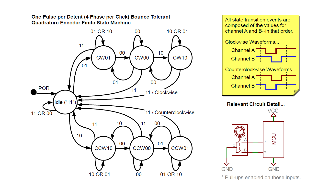
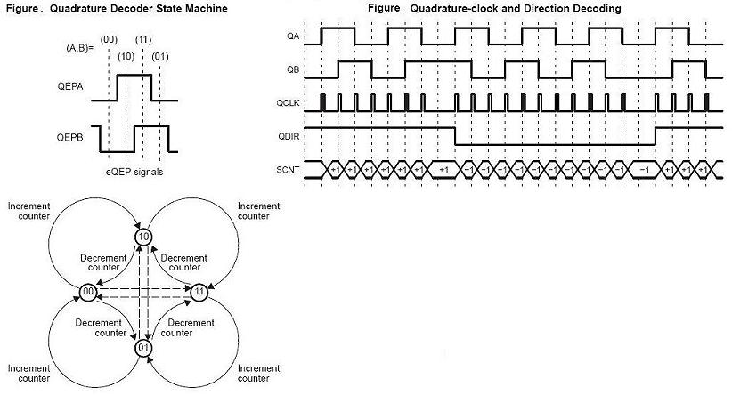
Typical finite state machine methods for handling quadrature inputs, by contrast, automatically debounce A and B inputs, either by ignoring cases where a set of inputs repeats, or by counting an equal number down and up transitions as bouncing occurs. See for example the diagrams in reply #17 in “easy rotary encoder implementation” at eevblog.com – from which the first diagram below is taken – and in Omapl137 linux eqep driver at ti.com, where the second diagram is from. Both those sources provide substantial detail about processing quadrature inputs.
Edit 1, part 2: Besides using a correct model of the quadrature process, encoder software should be fast, delay free, and asynchronous to other processing.
Slow handling of events (that is, of changes on encoder inputs) is caused by lengthy code or indirect IO, inter alia. Slow event handling cannot keep up with as many events per second as fast event handling; if code is really slow, users will notice that they have to turn or move an encoder at a snail's pace to avoid missing menu items or location steps.
Trying to handle events synchronously, eg via polling, also limits the rate at which software processes events. Unless a processor is quite fast or is dedicated to quadrature input, it is likely to miss occasional transitions on inputs. Using interrupts usually is a better choice when dealing with asynchronous transitions like encoder inputs.
By “indirect IO” I mean use of functions like digitalRead() and attachInterrupt() which result in massive overhead for IO processing.
digitalRead() takes between 3 and 4 μs to read one bit of input. Directly reading a port takes one instruction cycle, 62.5 ns (1/16 μs) on a typical Uno or Nano. If two encoder inputs are wired to the same port, one port read is enough, vs two digitalRead() calls. Note, this comparison assumes encoder pin numbers are known at compile time, that the target MCU is known, etc. With direct port IO, the programmer is responsible for making the software conform to the MCU, instead of having digitalRead() taking care of details like which port bit corresponds to which Arduino digital input.
attachInterrupt() adds about 5 μs of overhead to interrupt processing. [See the section “How long does it take to execute an ISR?” in Nick Gammon's interrupts page.] This is on top of about 2.6 μs of ordinary software overhead (for interrupts on Arduino Uno, Nano, etc.).
Note, some of the example code in previous answers uses attachInterrupt() and digitalRead(), but is concise enough to still get reasonable input rates. Using those functions leads to better code readability and portability. However, for faster input rates, you might use code as shown below. This code probably could be improved (shortened, made faster, made more clear) but anyhow functions ok for up to a few hundred counts per second. To adapt this code for other input pins, replace abNew = PINC & 3; by code to set the low two bits of abNew equal to the input bits; and adapt setup_rotocoder() accordingly. See (eg) Arduino Pin Change Interrupts and Simple Pin Change Interrupt on all pins for further information about setting up pin change interrupts.
// The following three vars should be visible to loop(), which
// can find out if an encoder changed by testing rotoInt.
static   byte roABold;          // A,B states for rotor
volatile uint16_t roCount;      // current rotary count
volatile byte rotoInt;          // Rotary-interrupt flag (change flag)

// jiw (c) 2015  Offered without warranty under GPL v3 terms as at http://www.gnu.org/licenses/gpl.html

ISR(PCINT1_vect) {  // This plus Arduino overhead of 2.6 us probably takes ca 5 us total per interrupt
  enum { upMask = 0x66, downMask = 0x99 };// up & down are complements
  byte roABnew = PINC & 3;  // Read pins  14, 15, which are A0, A1
  byte criterion = roABnew ^ roABold;
  if (criterion==1 || criterion==2) {
    if (upMask & (1 << (2*roABold + roABnew/2))) // Embeds state transition rules
      ++roCount;
    else --roCount;             // upMask = ~downMask
  }
  roABold = roABnew;            // Save new state
  rotoInt = 1;                  // Say something happened
}

// For rotary encoder initialization, in setup(), say:   setup_rotocoder();
void setup_rotocoder() {
  rotoInt = roABold = 0;
  roCount = 32768;              // Start with a middle count
  pinMode(A0, INPUT_PULLUP);    // pin 14, A0, PC0, for pin-change interrupt
  pinMode(A1, INPUT_PULLUP);    // pin 15, A1, PC1, for pin-change interrupt
  PCMSK1 |= 0x03;
  PCIFR  |= 0x02;             // clear pin-change interrupts if any
  PCICR  |= 0x02;             // enable pin-change interrupts
}


