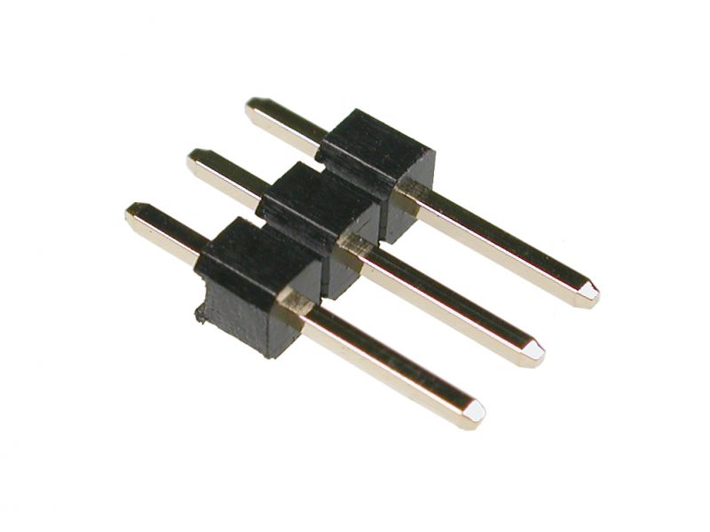
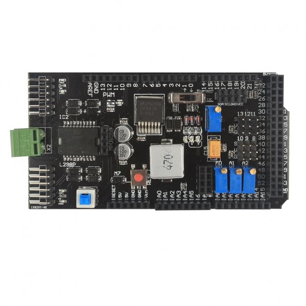
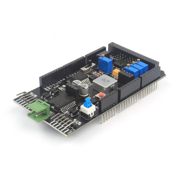
The SVG connectors on your board appear to be lacking header pins:
These should have been supplied with the board. If not you will need to source some. Either way, you will need to solder them on. I don't understand why they are not already attached.
If you look at the other images of the board on the SainSmart web page, the header pins are clearly visible:
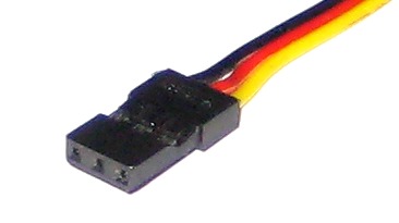
The S pin of each SVG is the same as the output pins, near the green light, but for ease of use, they are replicated in the SVG pins, so that a servo plug can be easily, and conveniently plugged in, with out the user having to wire up power and ground separately. If you look at the plug attached to the end of the cable coming from your servo, you will see the servo connector, like so:
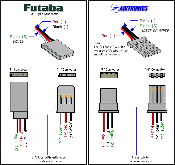
As the board has arranged the pins in the SVG order, that means that it will support the Futaba J type connectors (but not the Airtronics, as the power and ground pins are reversed):
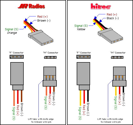
Also, Hitec and JR Radio connectors are supported by your board, as they have the same pin out:
For more information, take a look at Choosing RC Servos.
In addition, as Mikael says, you will also need to attach an external power supply to the green terminals
as the on board power regulator of the Arduino can not supply enough power to the servos, via the shield, by itself, neither with the USB, nor an external wall wart PSU, supplying power to the Arduino. So, use a bench power supply, battery pack, or otherwise and supply that power directly to the board via the Green power terminals at the end of the board.
Once you have done all of that, and got the hardware out of the way, then the software provided in Mikael's answer will work perfectly.

