2

Background

I'm trying to write code to read signals from a six-channel RC receiver on an Arduino Mega 2560. Currently I am keeping the code to just read one channel to make things easy to troubleshoot. The problem is my shared variable is not updating, leading me to believe that my interrupt service routine is not detecting any rising edges.

I thought my receiver was broken, so I tested it using the standard Arduino attach interrupt function. It worked perfectly, so my receiver is fine.

I used Serial.print() to see if my volatile channel variable was updating (that is, change its value to the channel 1 flag value). It was not updating, so my ISR must be wrong. You can find the original code in the blog post.

What's wrong? I'm out of ideas.

#include <PinChangeInt.h>

//Pin assignment
#define channel1PIN 10

//Bit flags
#define Channel1FLAG 1

//Flag holder
volatile uint8_t bFLAGUPDATESHARED;

//Shared variables: Accessed by the interrupt service routine and read in 'void loop'.
volatile uint16_t unCHANNEL1SHARED;

//Start time variables: These are used to set the start time of the rising edge of
//a pulse. They are only accessed by the ISR, and thus they are unsigned integers and
//not volatiles.

uint32_t ulCHANNEL1START;

void setup()
{
  Serial.begin(9600);
  Serial.print("RC Channel PWM Read Interrupt Test");

  //PinChangInt library function. Used to set attach interrupts.
  PCintPort::attachInterrupt(channel1PIN, calcCHANNEL1, CHANGE);
}

void loop()
{
  //In-loop variables to hold local copies of channel inputs.
  //This is static so it retains values between call loops.
  static uint16_t unCHANNEL1IN;

  //The in-loop copy of the bSHAREDFLAGUPDATE volatile flag holder
  static uint8_t bFLAGUPDATELOCAL;

  //Check to see if any channels have received signals. If so, copy
  //shared variables to local in loop variables.
  if (bFLAGUPDATESHARED)
  {
    //Switch off interrupts when I copy shared variables to local variables
    noInterrupts();

    bFLAGUPDATELOCAL = bFLAGUPDATESHARED;

    if (bFLAGUPDATELOCAL & Channel1FLAG)
    {
      unCHANNEL1IN = unCHANNEL1SHARED;
    }

    bFLAGUPDATESHARED = 0;
    interrupts();
  }

  Serial.println(unCHANNEL1IN);

  //Clear local update flags copy as all values have been copied to local variables
  bFLAGUPDATELOCAL = 0;
}

void calcCHANNEL1()
{
  if (digitalRead(channel1PIN) == HIGH)
  {
    //If pin goes high, start timer and set ulCHANNEL1START to timer start
    ulCHANNEL1START = micros();
  }
  else
  {
    //If it is not rising, it must be falling so set shared
    //variable to current time-start time
    unCHANNEL1SHARED = (uint16_t)(micros() - ulCHANNEL1START);

    //Tell that channel 1 has received a signal
    bFLAGUPDATESHARED |= Channel1FLAG;
  }
}
3
  • Try simplifying your code. Have the ISR light up an led, for example. I don't see anything inherently wrong.
    – Gerben
    Commented Mar 21, 2015 at 16:54
  • I figured it out. For some reason, it only works on pins 10,11 and 12. I don't know why though. PinchangeInt should work on any digital pin
    – Ozymandias
    Commented Mar 21, 2015 at 19:11
  • But you are using pin 10? Anyway; glad you got it working.
    – Gerben
    Commented Mar 21, 2015 at 21:28

2 Answers 2

4

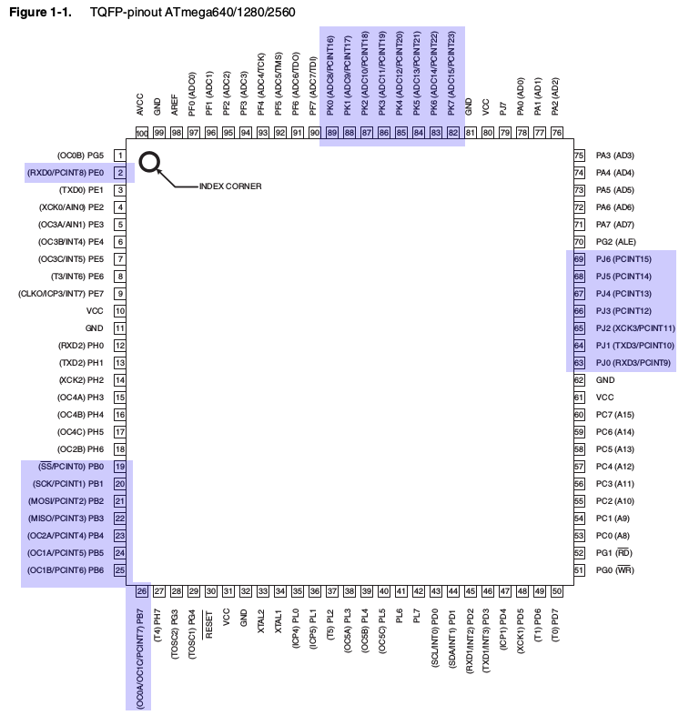
Only some ports on the Atmega2560 support pin-change interrupts, specifically ports B, E (bit 0), J (bits 0 to 6) and K.

Looking at the reference schematic that means that these pins on the board are supported:

     Chip
Name  Pin  Pin on board
-----------------------

Port B

PB0 - 19 - D53 (SS)
PB1 - 20 - D52 (SCK)
PB2 - 21 - D51 (MOSI)
PB3 - 22 - D50 (MISO)
PB4 - 23 - D10 
PB5 - 24 - D11
PB6 - 25 - D12
PB7 - 26 - D13

Port E

PE0 - 2 - D0 (RXD0)

Port J

PJ0 - 63 - D15 (RXD3)
PJ1 - 64 - D14 (TXD3)
PJ2 to PJ6 - not connected on board

Port K

PK0 - PK7 - (89 - 82)  - A8 - A15

Thus you can see that D10 to D12, which you say works, are in that list. Other random ones would not be.


SoftwareSerial

You can see confirmation on the page for SoftwareSerial where it says:

Not all pins on the Mega and Mega 2560 support change interrupts, so only the following can be used for RX: 10, 11, 12, 13, 14, 15, 50, 51, 52, 53, A8 (62), A9 (63), A10 (64), A11 (65), A12 (66), A13 (67), A14 (68), A15 (69).

This is because SoftwareSerial uses pin-change interrupts to detect incoming serial data, and thus the disclaimer on that page about which pins it will work with.


Atmega2560 pin-outs

Atmega2560 pin-outs


PinchangeInt should work on any digital pin

Note that the Atmega328P (as used in the Uno) has less ports, and all are available for pin-change interrupts on that board.

3
  • This can't be right. The page first linked by OP claims pins 2, 3, 18, 19, 20, and 21 can be used for interrupts. These map to PE4, PE5, PD3, PD2, PD1, and PD0, according to goo.gl/DvHEUA and goo.gl/xAwBGM For my part, I'm more concerne with whether PORTC can be used, as in ros_arduino_bridge: goo.gl/rq6yQO
    – tsbertalan
    Commented Dec 17, 2016 at 23:09
  • The linked page refers to external interrupts however the OP is using pin change interrupts as you can see from #include <PinChangeInt.h>. The pin change interrupt pins are the ones I listed.
    – Nick Gammon
    Commented Dec 18, 2016 at 1:14
  • I see. I had an inkling that might be the distinction, but assumed that all pins capable of external interrupts would also be capable of pin change, though not the other way around.
    – tsbertalan
    Commented Dec 19, 2016 at 3:53
2

On the ATmega1280/2560, only ports B, J, F, and K have pin change interrupt capability. These map approximately to pins 10 through 15, 50 through 53, and A6 through A15 (although part of port J is unmapped to Arduino pins, therefore PCINT11 through PCINT15 are unavailable on the Arduino Mega/Mega 2560).

Your Answer

By clicking “Post Your Answer”, you agree to our terms of service and acknowledge you have read our privacy policy.

Not the answer you're looking for? Browse other questions tagged or ask your own question.