0

What I want to do: attach six buttons to a single input. Each button triggers a different action.

How I want to do it: Use an AD conversion and add a resistor with different values to each button so that you can distinguish between the different input signals
I use these values: 1k, 4.7k, 18k, 22k, 55k, 300k

Vcc is stable 3.3v but I also tried it on 5v. I use Vcc as reference value for the ADC.

The problem I have: no matter what I do I always read the same value on the ADC. Connected to GND it reads 0 and on Vcc it reads a value that’s always the same regardless what resistor I actually use.

I tried a lot of things I’ve found on the internet but nothing really worked for me. I’m clearly doing something wrong

This is the method I call in setup() to initialize the converter on ADC2(pb4)

void initADC()
{
  // 8-bit resolution
  // set ADLAR to 1 to enable the Left-shift result (only bits ADC9..ADC2 are available)
  // then, only reading ADCH is sufficient for 8-bit results (256 values)

  ADMUX =
            (1 << ADLAR) |     // left shift result
            (0 << REFS1) |     // Sets ref. voltage to VCC, bit 1
            (0 << REFS0) |     // Sets ref. voltage to VCC, bit 0
            (0 << MUX3)  |     // use ADC2 for input (PB4), MUX bit 3
            (0 << MUX2)  |     // use ADC2 for input (PB4), MUX bit 2
            (1 << MUX1)  |     // use ADC2 for input (PB4), MUX bit 1
            (0 << MUX0);       // use ADC2 for input (PB4), MUX bit 0

  ADCSRA = 
            (1 << ADEN)  |     // Enable ADC 
            (1 << ADPS2) |     // set prescaler to 64, bit 2 
            (1 << ADPS1) |     // set prescaler to 64, bit 1 
            (0 << ADPS0);      // set prescaler to 64, bit 0  
}

The code is taken from here https://www.marcelpost.com/wiki/index.php/ATtiny85_ADC

The page seems to be down at the moment so here is an archived version of it https://web.archive.org/web/20230128091128/https://www.marcelpost.com/wiki/index.php/ATtiny85_ADC

In the loop() method I do basically this: Read ADC and then blink an LED n times, based on the read value.

ADCSRA |= (1 << ADSC);         // start ADC measurement
while (ADCSRA & (1 << ADSC) ); // wait till conversion complete 

uint8_t adcValue = ADCH;

if (adcValue >= 0 && adcValue < 32) {
  blink(1);
} else if (adcValue >= 32 && adcValue < 126) {
  blink(2);
} else if (adcValue >= 126 && adcValue < 193) {
  blink(3);
} else if (adcValue >= 193 && adcValue < 227) {
  blink(4);
} else if (adcValue >= 227 && adcValue < 245) {
  blink(5);
} else if (adcValue >= 245 && adcValue <= 255) {
  blink(6);
}
delay(60000);

My breadboard has the resistors going from Vcc to an empty row and I connect a jumperwire from PB4 to one of these resistors and do an external reset of the microcontroller to test my setup. They share GND/Vcc

What am I doing wrong? What can I do to debug this?

Thanks

11
  • 1
    you forgot to connect a resistor between analog input and ground ... research voltage divider
    – jsotola
    Commented Jul 28, 2023 at 23:38
  • Are you using an Arduino core which does not support analogRead() or is there another reason why you are directly reading ADC registers ? The ADC is 10bit so can read analog values up to 1023. Does your application allow for pressing two or more buttons simultaneously? If you have a multimeter you could check the voltage between the analog pin and ground when a button is pressed.
    – 6v6gt
    Commented Jul 29, 2023 at 3:45
  • Funnily enough, someone else also wanted to connect six buttons to an ATtiny85 to "Connect 6 buttons with 6 different resistors to a single ADC pin of the controller". It's an amazing coincidence!
    – Nick Gammon
    Commented Jul 29, 2023 at 7:29
  • 2
    @NickGammon I unfortunately can’t tell if you’re trying to be funny or sarcastic. It’s the same project but a different question.
    – boop
    Commented Jul 29, 2023 at 10:52
  • 1
    there is no schematic diagram in the question ... it is impossible to determine how the OP connected everything ... voting to close for being unclear
    – jsotola
    Commented Jul 29, 2023 at 20:37

1 Answer 1

1

Unfortunately @jsotola only posted their solution as a comment. But it was the correct answer. So I'll just post my solution here

I now use a voltage divider setup with these values:

Voltage divider formula Vs * R2 / (R1 + R2)

Vs: 3.3v
R2: 100k Ohm
R1: 10k (3.0v), 27k (2.8v), 38k (2.6v), 50k (2.2v), 65k (2.0v)

Using an 8-bit ADC, I came up with these if statements to distinguish between the inputs. I gave it some room for deviation

if (adcValue >= 227 && adcValue <= 237)
{
  // 10k ohm (3.0V -> adc 232)
}
else if (adcValue >= 212 && adcValue <= 223)
{
  // 18k ohm (2.8V -> adc 217)
}
else if (adcValue >= 196 && adcValue <= 206)
{
  // 27k ohm (2.6V -> adc 201)
}
else if (adcValue >= 181 && adcValue <= 191)
{
  // 38k ohm (2.4V -> adc 186)
}
else if (adcValue >= 165 && adcValue <= 175)
{
  // 50k ohm (2.2V -> adc 170)
}
else if (adcValue >= 150 && adcValue <= 160)
{
  // 65k ohm (2.0V -> adc 155)
}

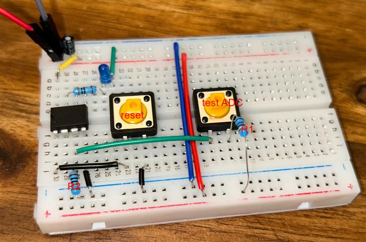
Here is a picture of my breadboard. I know it's not a real schematic but I couldn't figure that out right now. But I hope it's good enough

enter image description here

5
  • 2
    a comment is the only thing that was appropriate ... only a guess could be provided because of lack of information in the question
    – jsotola
    Commented Jul 29, 2023 at 20:39
  • I don't see six buttons here. Is this a work in progress?
    – Nick Gammon
    Commented Jul 29, 2023 at 22:55
  • 1
    @NickGammon I just inserted different resistors to test each of them one by one. That was easier than setting up 6 buttons and was good enough. Just needed to know if it works in general
    – boop
    Commented Jul 29, 2023 at 22:59
  • There seem to be some gaps in your ranges. For example, what if adcValue is 238? But perhaps that is deliberate. You could probably rewrite as only doing greater-than tests. For example, >= 227, then if it fails that, >= 212 and so on. Testing the other limit seems redundant.
    – Nick Gammon
    Commented Jul 30, 2023 at 1:48
  • It is not clear if it matters in this use case but a 65k resistor in parallel with a 50k resistor is effectively a 28.2k resistor. This is very close, allowing for tolerances, to the 27k resistor you are also using meaning that it could be difficult to distinguish between a single button press and at least some combinations of multiple button presses.
    – 6v6gt
    Commented Jul 30, 2023 at 2:24

Not the answer you're looking for? Browse other questions tagged or ask your own question.