I have a project where I would like to power an Arduino Nano 33 BLE Sense with USB and Vin at the same time.
The idea is to charge an external LiPo 3.7V through a charger module that would take the load from the 3.3V pin (that would be powered through USB) and at the same time keep powering the Arduino through Vin because I want to avoid a power interruption when I unplugged the USB cable that would interrupt the writing operation (on a text file on an SD card).
So the goal is to prevent data corruption on a writing operation on a text file. I know text files are supposed to be less corruptible (compared to a database) but I want to be sure the operation would be uninterrupted.
I've seen this post: What happens if I power the Arduino with both the USB and external power voltage simultaneously? But it's related to the Arduino UNO R3.
It basically says: When Vin >6.6V the opamp turns the mosfet off.
so the USB disconnects.
When Vin <6.6V the opamp turns the mosfet on.
so the USB stays connected.
On Arduino's website: https://store-usa.arduino.cc/products/arduino-nano-33-ble-sense it says:
Vin: This pin can be used to power the board with a DC voltage source. If the power is fed through this pin, the USB power source is disconnected.
It does not mention from what voltage it would disconnect the USB power.
I did not find the same schematic for the Arduino Nano 33 BLE Sense. Just this:https://docs.arduino.cc/hardware/nano-33-ble-sense
Interactive Viewer Interact with the schematics, the PCB and a 3D model of the product.
and this: https://docs.arduino.cc/static/353d3c445c28b1da1fe1f9d6eafa948d/ABX00031-schematics.pdf
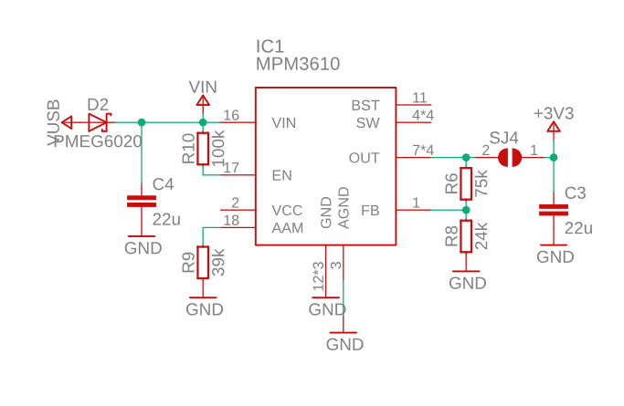
I'm not very familiar with reading schematics but I could not find similar information about vin and USBVCC.
That'd be great if somebody had some insight on that.
I would welcome any suggestion.
Cheers!
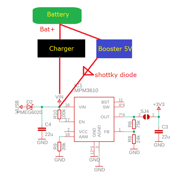
If I connect a battery charger/controller on VIN, my battery would be protected.
And I could connect a booster 5V and add a shottky diode so its connection to VIN would be closed if booster+ < VIN
Like this ?


