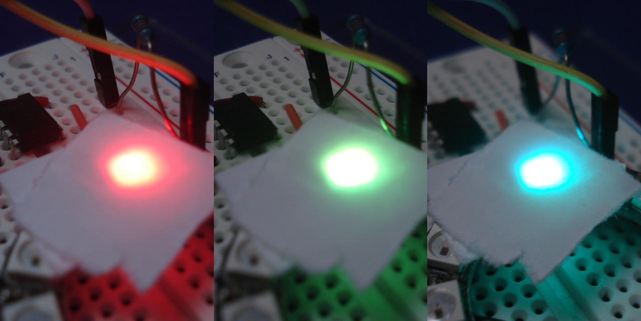
UPDATE Clock speed code has been tweaked as per the suggestion from @timemage due to inability for Wire library to reduce to below 30304Hz. Unfortunately problems still persist: Nothing printed out to serial and LED working only after disconnecting and reconnecting the circuit(stops updating after reseting arduino)..
UPDATE Thanks for all replys. I have left the circuit the same and have used the following code where i have tried to reduce the i2c clock speed to 1khz but unfortunately having no luck.The EEPROM returns nothing and the pixel fails to work initially, only when i disconnect the circuit(this is simple because i am using a magnetic USB connector) it seems to work fine(until i restart the arduino). If the consensus is that i may have more luck if I alter the library then i may look into it although it sounds a bit out of my depth...
#include <Wire.h>

#define disk1 0x50    //Address of eeprom chip
unsigned int address0 = 0; //address to store the data

#include <Adafruit_NeoPixel.h>


//pixels pin
#define sda_pin A4
#define scl_pin A5

Adafruit_NeoPixel strip(1, sda_pin, NEO_GRB + NEO_KHZ800);


void setup() {

  Serial.begin(9600);

  Wire.begin();

  ////UPDATED CODE TO REDUCE I2C CLOCK SPEED TO 1KHZ////
  TWSR |= 0x03; // chose divide-by-64 prescaler
  TWBR  = 0x80; // closest to 1 kHz from below at 16 MHz with /64 prescaler.


  Serial.println(readEEPROM(disk1, address0), DEC);
  Wire.end();
  pinMode(scl_pin, INPUT);


  strip.begin();           // INITIALIZE NeoPixel strip object (REQUIRED)
  strip.show();            // Turn OFF all pixels ASAP
  strip.setBrightness(100); // Set BRIGHTNESS to about 1/5 (max = 255)

}

void loop() {
  rainbow(10);
}


void rainbow(int wait) {

  static unsigned long timer = 0;
  static long firstPixelHue = 0;

  if (millis() - timer > wait) {
    timer = millis();

    for (int i = 0; i < strip.numPixels(); i++) { // For each pixel in strip...

      int pixelHue = firstPixelHue + (i * 65536L / strip.numPixels());

      strip.setPixelColor(i, strip.gamma32(strip.ColorHSV(pixelHue)));
    }
    strip.show(); // Update strip with new contents


    if (firstPixelHue < 5 * 65536) { //incrememnt
      firstPixelHue += 256;
    } else firstPixelHue = 0; //reset

  }
}


byte readEEPROM(int deviceaddress, unsigned int eeaddress )
{
  byte rdata = 0xFF;


  const uint8_t i2c_base_address = 0x50;
  const uint8_t upper_three_eeprom_adress_bits = (eeaddress >> 8) & 0x7;
  const uint8_t i2c_address = i2c_base_address | upper_three_eeprom_adress_bits;
  Wire.beginTransmission(i2c_address);
  Wire.write(eeaddress & 0xFF); // address LSB

  Wire.endTransmission();

  Wire.requestFrom(deviceaddress, 1);

  if (Wire.available()) rdata = Wire.read();

  return rdata;
}
ORIGINAL POST:
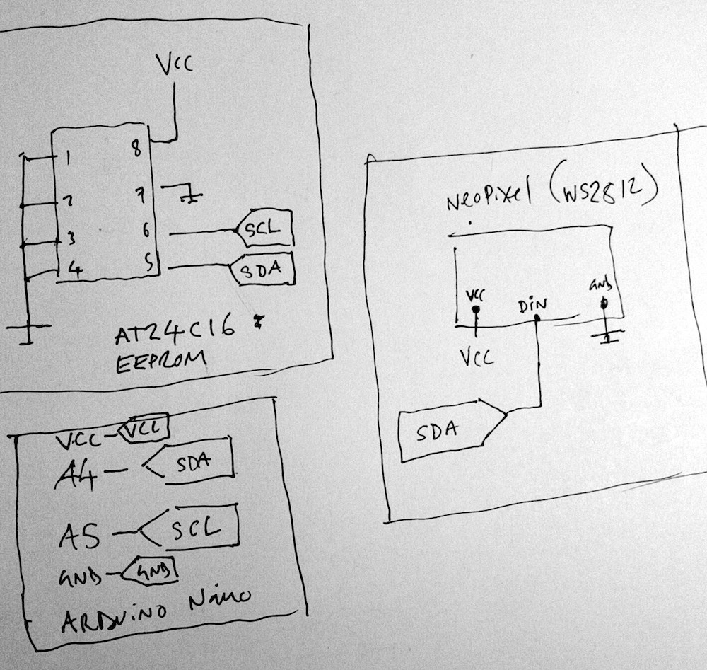
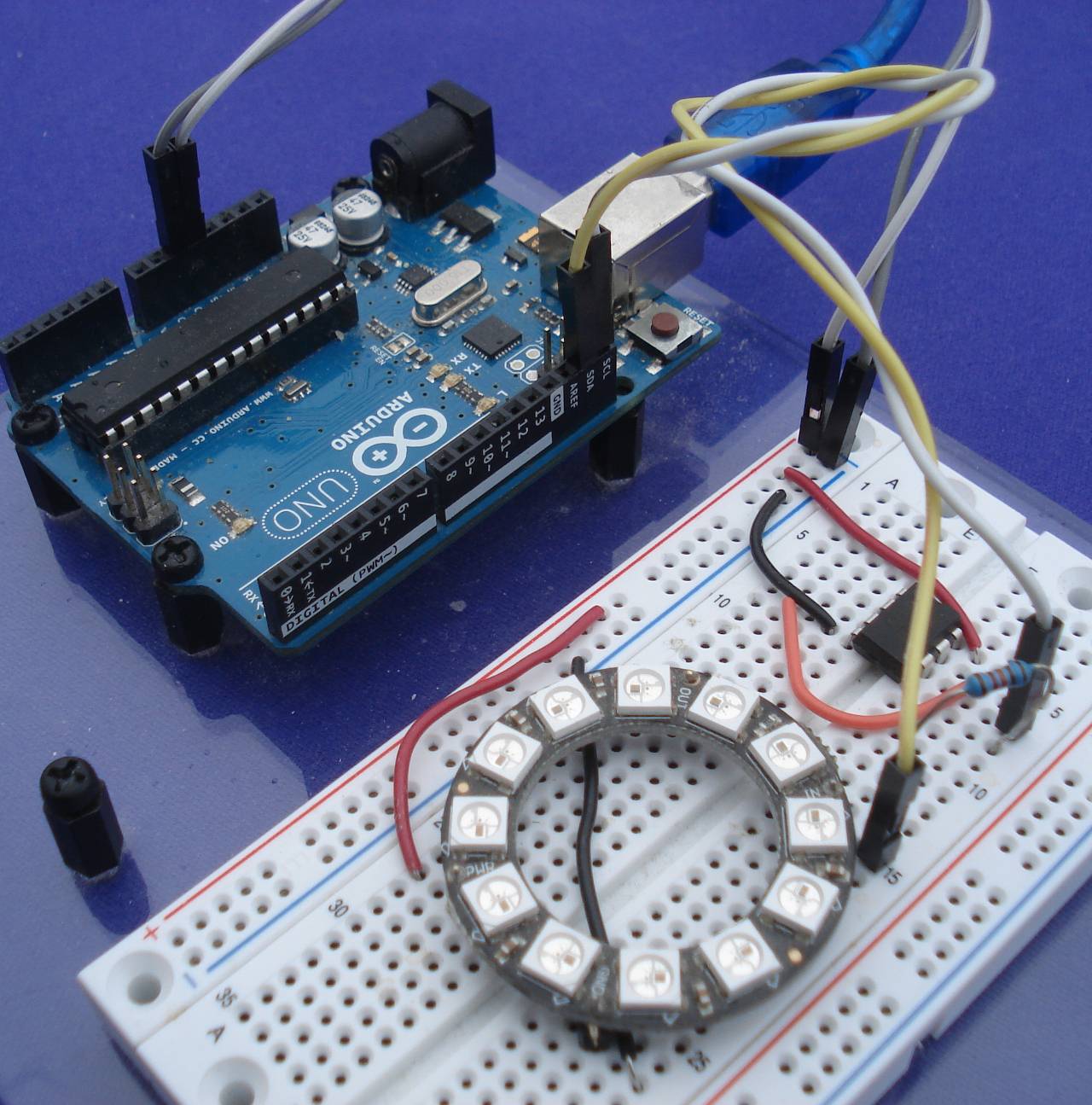
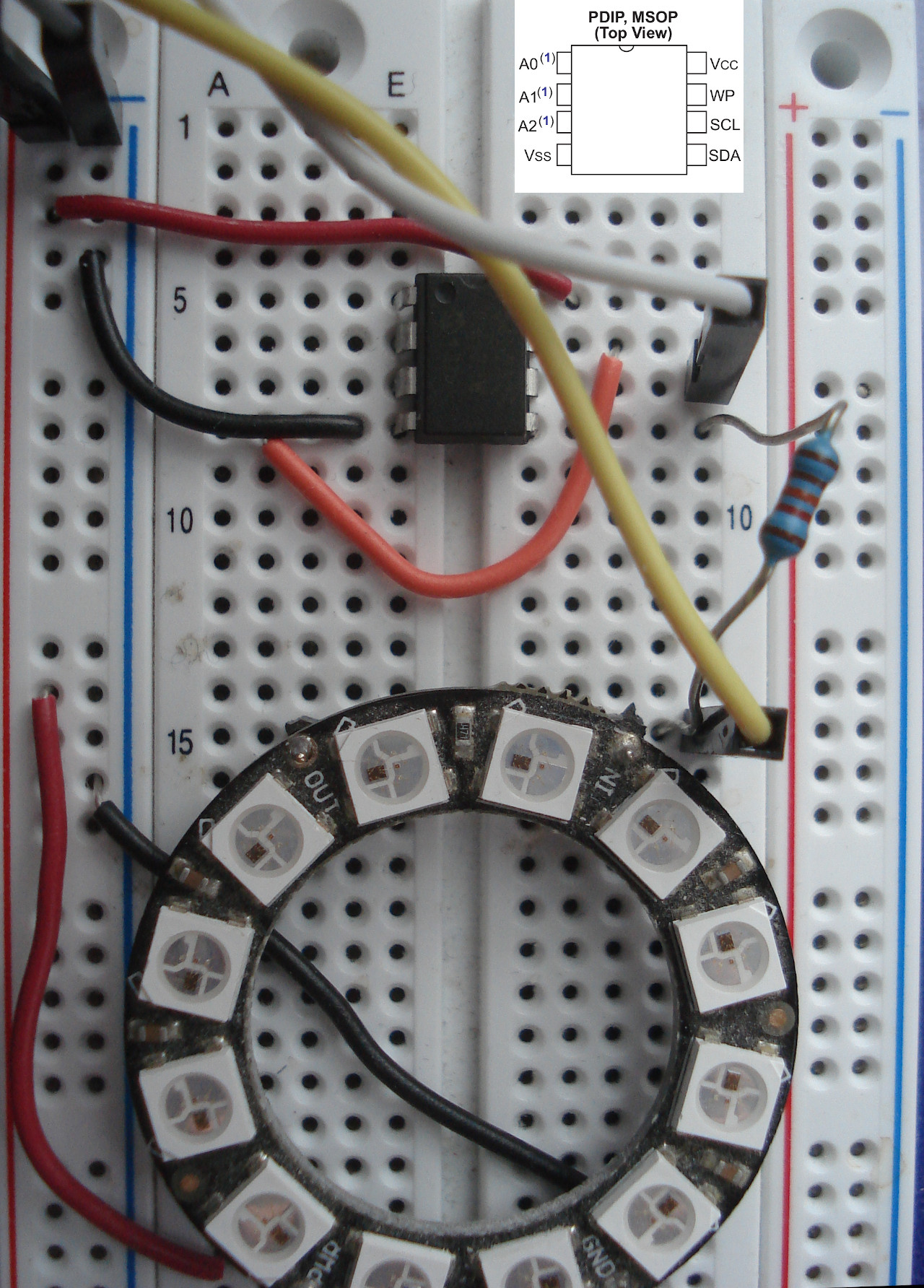
I have created a circuit which includes an AT24C16 EEPROM which I only need to read from and an addressable LED (WS2812 IC), which I will be talking to (Using an Arduino Nano).
My original intention was to attach the LED's DIN pin to either SCL or SDA. I thought that since I only needed to read the EEPROM once (and then control the LED), I would be able to share the connection. After creating the circuit, it proved an incorrect assumption.
I am limited to 4 (nets?) total due to the adapter I am using between the Arduino Nano and the rest of the circuit (repurposed magnetic 4 wire USB cable). Could anyone propose a setup which would allow me with only these 4 connections, to read from the EEPROM and write to the LED? As I mentioned, I only need a single read from the EEPROM to identify it and then I will only be writing to the pixel. Many thanks!
Attached is the schematic.

