Summary: The green TWI/I2C port on my Braccio shield I2C port hasn't worked for me so far. Looking for advice or information please.
Detail:
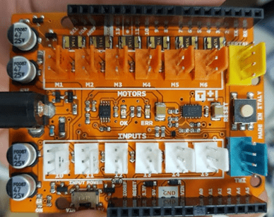
I'm using the Arduino (Tinkerkit) Braccio robot arm for self education. It comes with a Uno based Braccio Shield. Tinkerkit no longer seems to be in business and documentation is a bit scarce. The shield uses KF2510 style connectors for servos (orange), inputs (white), serial (yellow) and importantly for my question a TWI/I2C port (green).

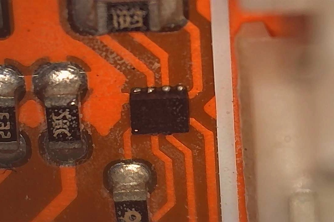
The green four pin TWI/I2C connector provides GND, +5V, SDA (A4), SCL (A5). However the SDA and SCL connections are reported to not be direct, but that "a very tiny chip (located next to the I4 connector) buffers between the green connector and the Arduino pins SDA and SCL" . A photo of the chip described is below.

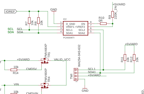
Contrary to the reports of a "buffer" studying the schematic shows a level shifter PCA9306TI and two sets of 10K pullup resistors (R7,R8 and R11,R12) on the bus on both sides of the chip. VREF2 on the outboard side of the chip has a R9 220K resistor to +5V.
The other side of my I2C connection was an Arduino Pro-mini 5V. I was never able to get it working using the green port described, but it works fine directly hooked into SCL and SDA bypassing the level shifter.
My questions (sorry for the long lead up) are:
- Has the green TWI port been level shifted to expect ~3V? (Only really came to this conclusion writing this all up clearly).
- If I want to change the green TWI port to 5V I2C can I replace R9 220K with a zero ohm jumper?
- The 10K pullups (R7,R8 and R11,R12) seem larger than anticipated (I had anticipated about 4.7K for 5v or about 2.4 for 3V)? Can they be removed and left open if I have a single set of pullups elsewhere on the bus? Or better suggestions?
Thanks!
Update 2021/01/30
Well my I2C debugging skills are improving researching this! As a test bed I set up a clean working I2C bus with two MCU's running the Arduino Example Master/Writer Slave/Receiver sketches by Nicholas Zambetti. I tested the I2C signal on the oscilloscope to make sure it was clean. All good. To that test bed I connected the Braccio shield (5V, GND, SCL, SDA). Connecting the Braccio shield changes the I2C signal in interesting ways, with partial strength (runt) pulses, and round shoulder slow rises. Connecting via the green TWI port seems to accentuate the runt pulse aspect. Also interesting the oscillscope was still able to decode the signal. Still working on figuring this out.
Pic 1. First test - SCA and SCL connected via pin headers in top left of shield picture above.

Pic 2. Second test - SCA and SCL connected via green TWI port
 Pic 3. Clean Signal (no Braccio Shield connection)


