5

I have arduino Pro Mini 3.3V version with hc-05 module connected to 3.3V/GND and RXI/TX0 pins. I am then using my android phone to connect to the module. It shows up and pairs fine. Then I use BlueTerm app to view the output. I am seeing output that is occasionally as expected but mostly partially corrupted (characters replaced with random characters).

I am using 9600 baud rate and trasmitting the following:

void serialTransmit(int data){
  // send to raspberry pi or other device(s).
  Serial.print("Serial Transmit: ");
  Serial.println(data); // this is hard coded as "12" for testing
}

I tried switching rx/tx pins around but got same corrupt output. Tried changing baud rate but then it wouldn't transmit anything at all and default rate is 9600 so that was expected.

What could be the cause?

6
  • Does it show up as expected when using a computer? Also, I've seen some models with 38400 baud Commented Mar 18, 2014 at 19:32
  • I don't have bluetooth on any of my pc's yet, could try a tablet but should it matter if it's android or another OS? ebay listing does say 9600 baud rate but will try 38400 later.
    – DominicM
    Commented Mar 18, 2014 at 23:00
  • Tablet should be fine, just to double check the reading. Could you also try setting the parity bit/etc. on BlueTerm? Commented Mar 18, 2014 at 23:12
  • Not seeing any such option in BlueTerm or other 3 apps I tried. It does seem odd that I get about 10 lines correctly at the beginning and only then it starts to corrupt.
    – DominicM
    Commented Mar 19, 2014 at 1:36
  • That's weird... Commented Mar 19, 2014 at 1:37

3 Answers 3

2

First thing to try:

Connect a 2.2k - 10k resistor from the arduino RX pin (the hc-05 tx pin) to ground.

If that didn't work, I recommend getting everything into a known state and eliminating some complexity. So, first let's remove the Android software from the equation. And second, let's put the module into a known baud rate.

To do this wire up the arduino and module like this:schematic
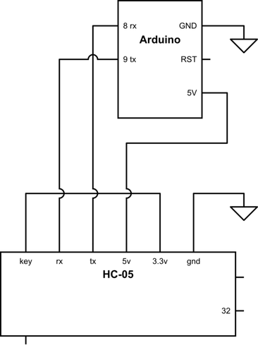
Notice that the Key pin is connected to 3.3v. That will ensure the module is at 38400 baud on power up.

Connect the arduino to your computer with the FTDI cable. Upload the following sketch:

/* Serial Loop */

#include <SoftwareSerial.h>

#define rxPin 8
#define txPin 9

SoftwareSerial mySerial(rxPin, txPin); // RX, TX
char myChar ;

void setup() {
  Serial.begin(9600);   
  Serial.println("AT");

  mySerial.begin(38400);
  mySerial.println("AT");
}

void loop() {
  while (mySerial.available()) {
    myChar = mySerial.read();
    Serial.print(myChar);
  }

  while (Serial.available()) {
    myChar = Serial.read();
    Serial.print(myChar); //echo
    mySerial.print(myChar);
  }
}

With the sketch now uploaded and running, open the Arduino serial console and enter these AT commands. The serial console baud rate should be set to 9600 and line endings should be "Both NL & CR"

AT+ORGL //back to factory settings
AT+ROLE=0 //slave role - transparent serial bridge
AT+UART=9600,0,0 //default baud rate
AT+INIT //init module

You should get "OK" back from the module after each command. If you've gotten this far, we know the module is working fine and we know what baud rate it will default to now.

Hook the module back up the way you had it before. Make sure 3.3v is disconnected from key pin and make sure you have added the pulldown resistor on the RX line. Cycle the power to the module. The module should start up running 9600 baud, slave mode. Delete the module from the Android pairing list and re-pair it. The name probably will have changed. Hopefully it works correctly now.

Cheers

10
  • I tried 4.7k resistor but it didn't make a noticeable difference, I assume there's no point in trying different resistor values? Also my module is bale, and has no voltage regulator, does your diagram apply to this situation since the module is rated at at 3.3V. Will need to wait until I receive my new soldering iron to change connections, clamping cables to the module is tedious :)
    – DominicM
    Commented Mar 19, 2014 at 1:47
  • I think I saw 2.2k recommended, but tried it and worked with 10k. The diagram applies except ignore the 5v line. You take 3.3v from the mini pro vcc pin to the BT module VCC and Key pin (pin 34).
    – imjosh
    Commented Mar 19, 2014 at 2:37
  • Until your soldering iron comes in, try using software serial instead of hardware serial. just move rx and tx on the arduino from 0 and 1 to some other digital pins. See my code as an example.
    – imjosh
    Commented Mar 19, 2014 at 2:40
  • If your wires are just clamped(alligator clips?) onto the module, you may just have a loose connection.
    – imjosh
    Commented Mar 19, 2014 at 2:47
  • I tried software serial but couldn't get any output, will try to get it to work tomorrow. It's not even alligator clips, it's a small hand clamp that's pushing the wires against the contacts on one side :) Connections seem solid though...
    – DominicM
    Commented Mar 19, 2014 at 2:51
0

I have the same problem with arduino pro mini and HC-06, only change the baud rate of your BTserial port... try diferent baud rates in my case:

Serial.begin(9600);   
Serial.println("AT");

BTSerial.begin(2400);
BTSerial.println("AT"); 

Works fine, it happens because the arduino try to "understand" the module, but if the module speaks other leanguage, the arduino will never understand the command.

like me... sorry for my bad english. se ya.

-1

Add the module as software serial then add these lines to setup() these line tell us the Bluetooth to turn into data mode:

bluetooth.begin(115200);
bluetooth.print("$$$");
delay(100);
bluetooth.println("U,9600,N");
bluetooth.begin(9600);

Your Answer

By clicking “Post Your Answer”, you agree to our terms of service and acknowledge you have read our privacy policy.

Not the answer you're looking for? Browse other questions tagged or ask your own question.