9

I have a custom Arduino ATMega328 board that generally runs at 5V @ 8MHz (using the Arduino Pro 3.3V 8MHz profile and bootloader). The main reason I'm using this setup is so that I can put the board to sleep when main power is disconnected and it starts being run off of battery power (3V from a coin cell). The 5V and 3V sources are diode OR'ed together and the 5V input is tied to INT0. In code, when it detects that INT0 has fallen low, it initializes sleep mode and everything powers down with the exception of the watchdog timer that keeps a 1Hz cycle to keep an internal count and check it the chip should be woken back up. This works beautifully when 5V power is applied first, then the battery is inserted, then 5V is disconnected. It goes to sleep and when 5V is brought back it wakes up and I can see it hasn't lost count.

However, the problem comes when 3V is applied first. I'm honestly not sure if it's even booting. But what it is supposed to do is boot, check if INT0 (Digital 2) is low and, if so, go right to sleep. By watching the current draw I see that it powers up to a few mA for a couple seconds, then drops to about 0.3mA (still higher than it should be in sleep mode). But when I re-apply 5V, nothing. The power draw goes back up but it is unresponsive (over FTDI serial).

Is there maybe something I'm missing that it can't be booted on 3V... in theory it should run just fine.

Update: I dropped an LED onto D13 and tried the blink sketch. Works fine when starting from 3V or 5V. However, when I run my firmware and start it from 3V, the LED just starts flashing wildly. I have no idea what's causing it since I never even setup D13 as anything in my code. But it makes me thing it's something to do with the bootloader...

9
  • 1
    What is the BOD set to, and what is the current draw on startup? Commented Mar 13, 2014 at 3:36
  • It's set to 2.7V. Current draw while at 3V is about 4mA for the first few seconds, then drops and the LED goes crazy.
    – Adam Haile
    Commented Mar 13, 2014 at 3:39
  • Have you tried without the bootloader, i.e. via ISP? Commented Mar 13, 2014 at 3:41
  • No, I haven't tried that yet. What's weird is it's fine when just running the blink sketch
    – Adam Haile
    Commented Mar 13, 2014 at 3:43
  • 2
    Can you add a diagram to show "exactly" how your wiring is connected, including any and every sensor or load on the battery. What kind of coin cell are you using, is it a Lithium Ion (rechargeable) or alkaline?
    – Ron J.
    Commented Mar 16, 2014 at 13:03

3 Answers 3

6
+100

So... turned out what was happening was all in code. Turns out that I was initializing an interrupt on INT0, when it was low, at the very beginning of my code. Problem was that when it started up on 3V backup power, INT0 was always low because INT0 is tied to the 5V line (it's how it knows to go to sleep). Because INT0 was low and the interrupt was triggering on low it was causing a constant interrupt to occur, never giving the rest of the program any time to run. Switched to enabling that interrupt only once I've entered full waking mode and it works fine now.

0
4

Exactly what is happening and why cannot be determined based on the amount of info provided. However, I see at least one potential problem which would at least partially explain the symptoms described.

You said that you are using diodes to select the voltage supply, and one supply is a 3V battery. If you are using standard diodes that drop ~0.6V then the supply voltage to the MCU is only ~2.4V. If you are using Schottky diodes with a voltage drop between 0.15-0.45, the supply voltage is potentially as low as 2.5V. You have the BOD voltage set to 2.7 volts, so in theory the MCU will never boot with the battery.

As for why you can start it at 5v, drop to 3v, and bring it back up again- I'm not sure. You could be disabling the BOD in code...maybe… Not sure why it works, but it's likely not guaranteed to work.

I setup a diode switch circuit with 5v and 3.3v to see what it looks like on my oscilloscope when the voltages switch. When at 3.3v switching up to 5v, the voltage oscillates quite a bit initially. This may potentially cause some problems when the MCU tries to come out of sleep. Putting a cap between VCC and GND smoothed the signal very nicely. When switching from 5v to 3.3v, there really wasn't any oscillating, just a clean drop.

From this information, it seems that you should lower the BOD threshold or turn off the BOD, and put a decoupling cap between VCC and GND. You probably also should make sure you have a pull-down resistor on INT0, and read the MCU datasheet sections explaining the various sleep modes all the considerations for sleeping and waking – it’s pretty involved. Cheers

2

I think the problem is with your bootloader, but not in the way you think.

When an Arduino starts up, a bootloader profiting several tasks, such as looking for a serial host or loading program data from flash is going to take a lot more energy than a sleeping Arduino.

I think the reason why your Arduino will not start is because the bootloader requires an accurate clock source, but applying 3v to it will mess up that clock and it will perhaps crash or wait for 3.3v to be applied for a stable source.

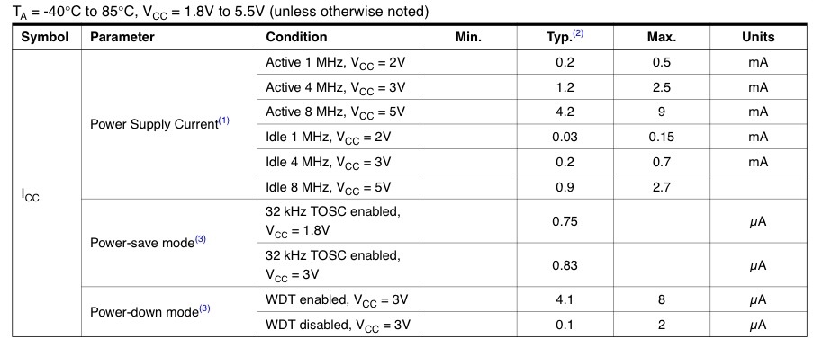
Looking at the datasheet:

copyright ATMEL

We see that current draw while waking up (running the bootloader) is probably going to be around 2mA, while sleeping current is about 0.8 microamps. This could certainly lead to a blackout on startup without the proper current.

Perhaps you should only turn it on with 5v power, or maybe you need a higher current, higher voltage battery.

1
  • Wouldn't this mean that Blink wouldn't work either? Also, I'm running more than a few Arduino's from coin cells with no issues. They can provide a lot of current for a short time. Commented Mar 16, 2014 at 17:15

Your Answer

By clicking “Post Your Answer”, you agree to our terms of service and acknowledge you have read our privacy policy.

Not the answer you're looking for? Browse other questions tagged or ask your own question.