2

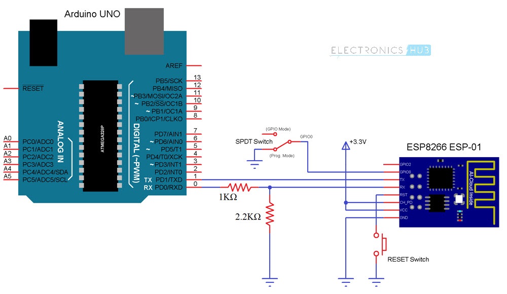
Well hello, experts, I've been trying to fix my issue all time, but all in vain. I have an Esp8266-01 with 1MB memory. I've flashed it with an official AT firmware V2.0.0 of espressif with the help of this tutorial-arduino as a usb/TTL-: "https://www.allaboutcircuits.com/projects/flashing-the-ESP-01-firmware-to-SDK-v2.0.0-is-easier-now/", and it was a successful flash. However, when trying to send AT commands in the serial monitor at different baud rates nothing happens. I'll provide you with all the information down here:

  1. Schematic for both flash and normal mode:

Schematic

  1. I used the official flasher tool from espressif

  2. I used both Arduino IDE and Termite with no results

  3. I've uploaded the blink sketch successfully into my module, but it never runs and blinks.
  4. After lots of tries and resets I started to receive some information: Reset info
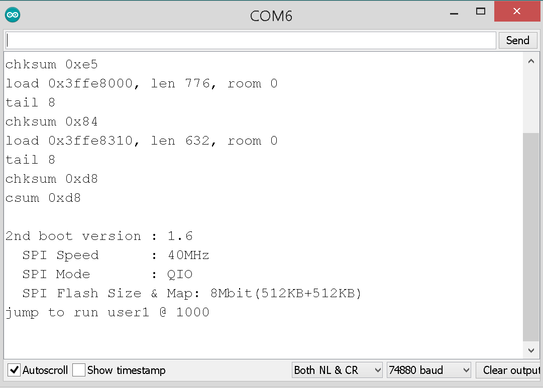
But still no answers from this module!!! Could you help me, please?

2 Answers 2

2

The tutorial is to flash SDK 2.0 AT firmware. The AT 2.0.0 firmware is build with RTOS SDK. The 2.0 AT firmware available on Espressif site was build with settings not compatible with esp-01. It is built for 2 MB flash and communicates over pins 13 and 15.

The latest NonOS SDK AT firmware is 1.7.1 (SDK 3), but it requires 2 MB flash too. It is possible to flash it to 1 MB module with the 2MB-c1 parameter with esptool.py. (The OTA update command will not work.)

GitHub user loboris (Boris Lovosevic) builds customized versions of AT firmware with SDK 3 for all flash sizes. You can download the files from his ESP8266_AT_LoBo GitHub repository. If you can't run his flash.sh utility, then for 1 MB flash you can Flash Download Tool with bin/upgrade/esp8266_AT_1_2.bin file and the right addresses for 1 MB flash: boot_v1.7.bin on 0x0; esp8266_AT_1_2.bin on 0x01000; esp_init_data_default.bin on 0xfc000 and blank.bin on 0x7e000 and 0xfe000.

1
  • Comments are not for extended discussion; this conversation has been moved to chat.
    – VE7JRO
    Commented Dec 23, 2019 at 15:05
0

You need pullup resistors, 10kΩ or so, on both the NRST and GPIO0 lines. After you press and release the reset button the NRST line will be floating, and its voltage (and logic level) will be undefined. It's not unusual to see the behavior of a board change just by waving your hand over it if you leave inputs floating, so it's not surprising that you will sometimes get it to work.

4
  • Thanks for this great help, and I'll give it a try right away.
    – Djf N4S
    Commented Dec 20, 2019 at 15:59
  • I just noticed that the TX/RX connections are incorrect. The TX from the Arduino should have the voltage divider and should feed into RX on the ESP-01. The TX from the ESP-01 should be connected to the RX on the Arduino. Ideally you would have a proper level translator between the 5V Arduino and the 3.3V ESP-01, but this might work. Commented Dec 20, 2019 at 16:26
  • Ah, never mind that last comment. It looks like you must be using the ESP-01 in place of the Arduino microcontroller. I initially thought that you were using the Arduino microcontroller to talk to the ESP-01. Commented Dec 20, 2019 at 16:31
  • That's it, I used the arduino board as a bridge in order to communicate with my esp8266.
    – Djf N4S
    Commented Dec 20, 2019 at 16:38

Your Answer

By clicking “Post Your Answer”, you agree to our terms of service and acknowledge you have read our privacy policy.

Not the answer you're looking for? Browse other questions tagged or ask your own question.