2

I am having a behavior I cannot explain while using arduino mega as a I2C slave for a raspberry pi master.

I am showing here an idealised program that shows the issue. I experience pretty much the same behavior in the real application (a keyboard firmware). What I am doing is the following:

  • the arduino issues an interrupt on pin 23 at evert loop to inform the raspi that there's some data to be read.
  • the raspi sends a request as master to the arduino.
  • arduino receives the request in the Wire handler, and issues a reply of 32 bytes. I fill these 32 bytes with a uint8 counter just as a check.
  • the cycle starts again.

This is the code for the raspi

import time
import RPi.GPIO as GPIO
import smbus

GPIO.setmode(GPIO.BCM)
GPIO.setup(4, GPIO.IN, pull_up_down=GPIO.PUD_DOWN)

bus = smbus.SMBus(1)
address = 0x42

def callback(channel):
    data = bus.read_i2c_block_data(address, 0x00, 32)
    print(data)

GPIO.add_event_detect(4, GPIO.RISING, callback=callback)

while True:
    time.sleep(1)

GPIO.cleanup()

and this is the code of the arduino

#include <Wire.h>

byte IRQ_PIN = 23;

volatile unsigned int counter;

void setup() {
    Serial.begin(115200);

    pinMode(IRQ_PIN, OUTPUT);
    digitalWrite(IRQ_PIN, LOW);
    Wire.begin(0x42);
    Wire.onRequest(requestEvent);
    Wire.onReceive(receiveData);

}

void signalMaster() {
  noInterrupts();
  irq();
  interrupts();
}

void irq() {
  digitalWrite(IRQ_PIN, HIGH);
  digitalWrite(IRQ_PIN, LOW);    
}

void requestEvent() {
  byte buf[32];
  counter++;
  memset(buf, counter, 32*sizeof(byte));
  Wire.write(buf, 32);
}

void receiveData(int byteCount){
  while(Wire.available()) {
    Wire.read();
  }
}

void loop() {
  signalMaster();
  delay(1);
}

As you can see, the point is that I am banging the I2C really, really fast, and the loop is very tight and fast. This is the point of the exercise and the problem to solve arises from this.

Now, once in a while I get an occasional IO error with the raspi python code. This code occasionally fails once, and then everything resumes to normal, but once in a while, it completely breaks down and never recover.

I attached a logic analyser to it, and this is what I found. D3 is the interrupt pin. The others the I2C bus. In a normal transaction, I can see everything working properly (disregard the different content of the response, it was an earlier run)

enter image description here

and a zoom in to the master request and the reply:

enter image description here

When I have a permanent failure, however, the picture is very different

enter image description here

Zoom in:

enter image description here

This makes little sense to me. Why would it perform a data write, and who is writing 0x85FF... in my buffer?

Thanks

14
  • 1
    The format is perfectly fine for an actual multi-byte write transaction. It's like the Python library is calling write_i2c_block_data instead of read_i2c_block_data. It must be some bug at the Raspberry end of things, possibly in the py-smbus library.
    – Majenko
    Commented Oct 13, 2019 at 22:50
  • i'll do some debugging tonight. Commented Oct 14, 2019 at 18:11
  • @Majenko Ok, from a brief check of the current code, the smbus module is a direct call to i2c_smbus_access, which then just performs an ioctl... so if there's a bug, this goes quite deep. As a curiosity, could the fact that I am using 3.3v vs 5v be a factor? I read conflicting opinions on pairing arduino and raspi without a level shifter in the middle. Commented Oct 14, 2019 at 19:07
  • The voltage difference wouldn't cause the Pi to perform a completely different transaction.
    – Majenko
    Commented Oct 14, 2019 at 19:52
  • It might be complete nonsense, but dissabling interupts on the arduino, than triggering the raspi, and than enabling the interupts sets the arduino in a state where it can not react on (now possible) I2C/SMBus interrupts.The raspi is really fast compared to the arduino and there might be a race condition. I admit; I do not believe in this solution myself, but if there no other solution it's worth a try ;-). How do you power/pull up the I2C bus. The resistors might be to high. Your Logic analyzers are no oscis. It shows you the logic levels not the real Voltages. Th. might also be a problem. Commented Oct 22, 2019 at 9:24

1 Answer 1

2
+25

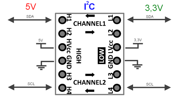
Use a logic level conversion IC. enter image description here

picture source http://msx-elektronika.pl/en/logic-level-converter

4
  • I bought two, I'll give it a try this weekend Commented Oct 25, 2019 at 10:38
  • @StefanoBorini, results?
    – Juraj
    Commented Nov 1, 2019 at 13:33
  • I added the logic level converter but I still get the same kind of errors. I am unsure at this point what is the reason. I decided that for the time being I just use a traditional keyboard microcontroller, but it's definitely something I have to revisit. I am adding a picture of my setup later tonight Commented Nov 4, 2019 at 16:39
  • @StefanoBorini, ok. I collected the half of the bounty and two upvotes, so if you now or in the future want to put a bounty on a question, write a comment here and I will put a 50 points bounty on that question (but only if I can't write a useful answer to it :-) )
    – Juraj
    Commented Nov 4, 2019 at 16:46

Your Answer

By clicking “Post Your Answer”, you agree to our terms of service and acknowledge you have read our privacy policy.

Not the answer you're looking for? Browse other questions tagged or ask your own question.