0

I have a problem similar to these questions:

Wemos D1 doesnt drive Relay

Wemos D1 is not triggering Relay

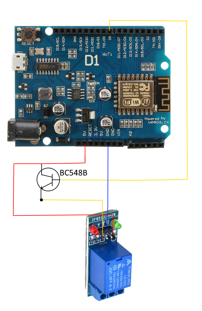
I got this BC548B transistor from an old apparatus I scratched. The transistor saturation voltage is 0.6V according to the datasheet:

https://alltransistors.com/pdfdatasheet_fairchild_semi/bc548_bc548a_bc548b_bc548c.pdf

When I set up my circuit the wemos d1 inboard leds dim and the board resets so I guess something is going really wrong. Can someone advise if my design makes sense?

enter image description here

UPDATE

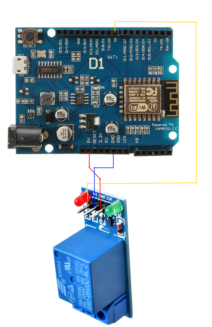
I replaced the 12V relay with a 5V one but still can't get it to work. Basically, the 3.3V signal seems to be too low to activate the solenoid. How can I raise the 3V3 signal to 5V? What was wrong with my idea of using a transistor to do it?

enter image description here

4
  • so the relay doesn"t activate with 3.3 V as HIGH?
    – Juraj
    Commented Jun 20, 2019 at 12:08
  • 1
    It makes no sense. Is that really the relay you are using? It has a transistor on there already. And did you see the voltage of the relay...?
    – Majenko
    Commented Jun 20, 2019 at 12:08
  • @majenko 1. Yes, that's the relay, It looks like I need 12V to feed it. In the other hand, if I feed with 5V and the control signal is 5V it works,I have tested it so I though if I can use the 3.3V signal to control the transistor, it should saturate with that voltage and work as a switch for the 5V signal I need. Commented Jun 20, 2019 at 13:08
  • Without knowing the schematic of the relay we cannot predict what is going on. I would suggest that you don't want a transistor at all - just directly drive the IN pin.
    – Majenko
    Commented Jun 20, 2019 at 16:45

1 Answer 1

2

That appears to be a 12 "solid state" relay. That means that it is designed to be both powered by and switched by 12V. You're trying to drive it with slightly more than 1/3 of its rated voltage. Don't do that.

Edit:

Note that none of the relays being discussed are true solid state relays. These are are all conventional coil relays that include cicuitry that allows them to be driven by CMOS logic signals. A true solid state relay does not have any moving parts, but uses solid state components to do the job of a relay. Those cost significantly more money however.)


It might be that you can get away with driving a 5V solid state relay with 3.3V, or 12V relay with 5V, but you shouldn't do those things either.

Also note that even if you are using the correct relay, your relay almost certainly takes more current than the 5V pin on an Arduino can provide (When driven from USB, the entire system is limited to 500 mA, including the power needed to the Arduino.)

Edit:

These solid state relays come in 12V, 5V, and 3V flavors. Get a 3V one: https://www.adafruit.com/product/3191?gclid=EAIaIQobChMIyY_dxM344gIVELbICh1ufwivEAQYBSABEgI3wPD_BwE

4
  • 1
    This answer is so wrong. This is not a SSR. And there is 5VDC on it. And the relay on link is not SSR either.
    – Juraj
    Commented Jun 21, 2019 at 16:02
  • this is a SSR module seeedstudio.com/Grove-Solid-State-Relay-V2-p-3128.html
    – Juraj
    Commented Jun 21, 2019 at 16:10
  • Vendors use the term solid state relay when they really shouldn't. It's a relay module with circuitry that enables you to switch it with low current logic level signals. I was being lazy by using that term, and should not have.
    – Duncan C
    Commented Jun 21, 2019 at 19:05
  • i added a note to point out that these are not really solid state relays. (And the relay I link to is a 3V relay. Look at the picture.)
    – Duncan C
    Commented Jun 21, 2019 at 19:09

Your Answer

By clicking “Post Your Answer”, you agree to our terms of service and acknowledge you have read our privacy policy.

Not the answer you're looking for? Browse other questions tagged or ask your own question.