3

I have an Arduino uno board and I have a soil moisture sensor

  1. connected the digital output pin of the sensor to Arduino input pin
  2. connected an output pin of Arduino to the INPUT pin of the relay board
  3. programmed the Arduino such that if input is HIGH then the OUTPUT should be HIGH as well
  4. connected 5 v pin of Arduino to vcc of the relay board
  5. connected gnd pin of Arduino to gnd of the relay board

When my sensor outputs a HIGH DO (digital output), the relay only creates a feeble click sound and does not get activated. The Relay board LED does light up but the relay itself does not work (NC remains closed and NO remains open).

Do I need to supply an external VCC to the relay board? If yes then how should I set up the circuit?

A picture of the relay board is attached. You are right ... it is a 12 v relay. Do I need a 12 v external power source with IN1 coming from Arduino? Any help will be much appreciated.
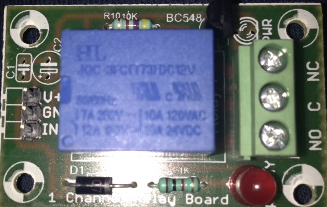
Relay

6
  • What relay do you use? if this one hobbyist.co.nz/sites/default/files/pictures/dancing-lights/… then yes you need to add power to the board. There are GND and VCC pins. Ground and +5V
    – Martynas
    Commented Dec 12, 2014 at 8:54
  • Yes. The relay is the one that you have shown except that it is single channel. So instead of connecting the VCC of the board to the 5v from the ARDUINO, I should connect the VCC of the board to an external 5v source and similarly I should connect the GROUND of board to GROUND of the external source? Commented Dec 12, 2014 at 9:41
  • no. Realy shield Vcc > Arduino +5V. And IN1 to arduino digital pin. If this not works, provide the code. Also, one of the gold rule, 99% there is no connection where it should be, or there is a connection where it shouldnt :) Check the wiring. Check this hobbyist.co.nz/?q=interfacing-relay-modules-to-arduino
    – Martynas
    Commented Dec 12, 2014 at 10:12
  • Sounds like you are using a 12v relay. Can you provide a link to where you bought it, or a part number?
    – Gerben
    Commented Dec 12, 2014 at 14:12
  • 40mA (max output current for arduino port) isn't a lot for a relay. Obviously we can't see what you're using to check that - but I would expect you to need a transistor for reliable operation. Commented Dec 12, 2014 at 16:08

1 Answer 1

6

You need to join the ground of the external supply to the ground being supplied from the Arduino. The 12V supply must be capable of at least 100ma

There appears to be a transistor and resistor on the board. This is probably to drive the relay coil from the Arduino. However, I would need to look at the circuit diagram of the board to be certain. Can you supply images of the copper side and component side of the board to see what the connections are.

Ideally the circuit diagram from the manufacturer would be even better.

Your Answer

By clicking “Post Your Answer”, you agree to our terms of service and acknowledge you have read our privacy policy.

Not the answer you're looking for? Browse other questions tagged or ask your own question.