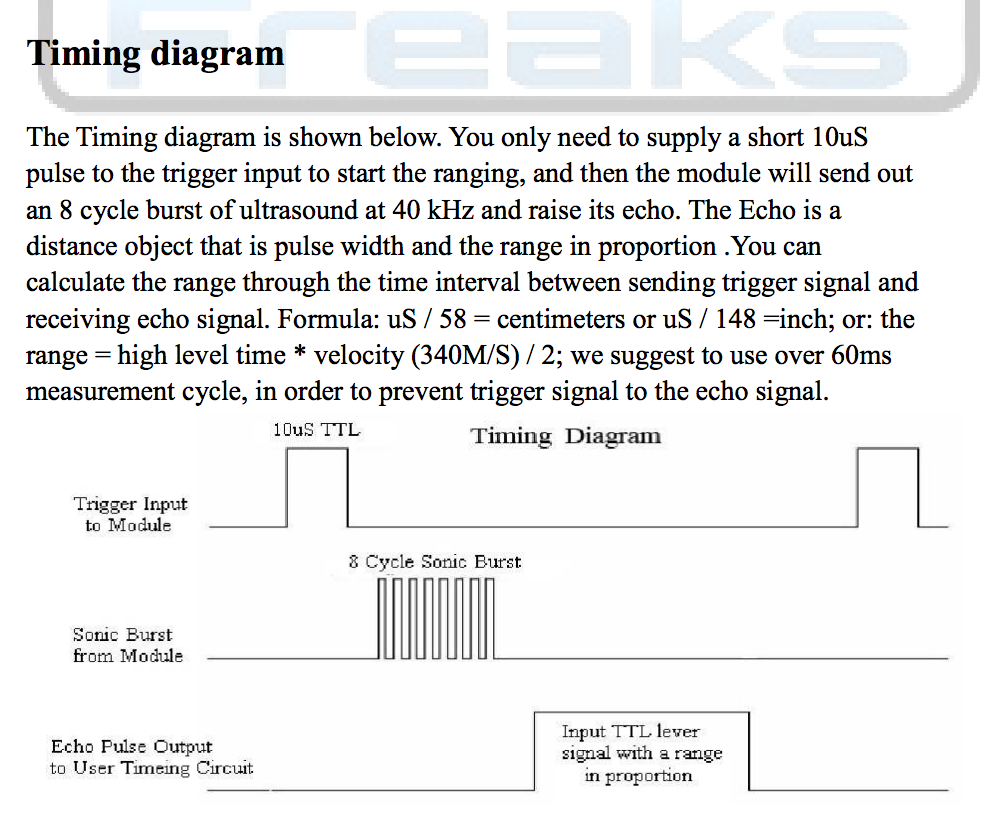
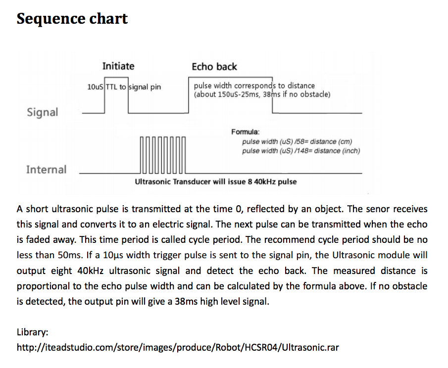
The specification1 says (emphasis is mine):
using IO trigger distance, the high signal to at least 10us.
So, longer than 10 μS is not a problem.
With respect to less than 10 μS, well 5 μS may also work, but it is out-of-spec and therefore not guaranteed to work and so may not always work correctly, or as expected.
From Source 1:

From Source 2:

As to why must it be 10 μS, well that is probably (at a guess) down to the design of the logic upon the silicon and the resultant propagation delay through the logic gates. Most, if not all, logic ICs specify a minimum amount of time required for a signal level, in order to allow the signal to propagate through the transistors that make up the logic, so that they switch correctly. PN junctions require a finite time for the electrons and holes to move, and when there are a number of them in sequential stages, that time is multiplied by the number of stages that the signal needs to propagate through. That is a very simplified way of looking at it.
To confirm this, you would need to speak to either the designers, or take a look at the mask used to fabricate the IC. Test simulations were probably run during the design phase, and they suggested a minimum trigger pulse of 10 μS. The figure could also be arrived at by simply looking at the design and counting the number of stages and multiplying that by the propagation delay per stage.
However, as Valbhav points out, the HC-SR04 is controlled by a STM8 (actually it is a STC11F), and after having looked at the STM8 programming manual, it is more related to instruction cycles. The Trig pin is, I assume, an interrupt, and from section 3.2 CPU registers
When an interrupt occurs, the CPU registers (CC, X, Y, A, PC) are pushed onto the stack.
This operation takes 9 CPU cycles and uses 9 bytes in RAM
So, 9 CPU cycles just begin to to service the interrupt, and then however many needed to actually do the rest. I can't find any timing diagrams in the Programming Manual which would show the minimum interrupt signal length. This information, is however in the Reference Manual
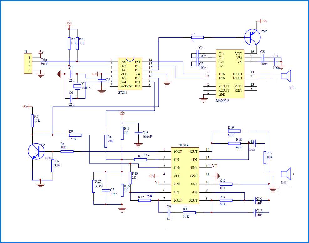
The length of a CPU cycle will obviously depend upon the clock frequency., which according to this schematic, from An Ultrasonic Shortcut – Getting the HC-SR04 Transducer Up and Running Fast!, is 4 MHz:

So, 10 μS is 40 CPU cycles.
1 Sources for downloading HC-SR04 pdf datasheet:
HC-SR04 Specifications
- Working Voltage: DC 5V
- Working Current: 15mA
- Working Frequency: 40Hz
- Max Range: 4m
- Min Range: 2cm
- Measuring Angle: 15 degree
- Trigger Input Signal: 10µS TTL pulse
- Echo Output Signal Input TTL lever signal and the range in proportion
- Dimension 45 * 20 * 15mm


