0

NOTE: This is not a question that has been answered previously in similar questions. I am using an arduino Mega

I have gone through Bergers Blog(schematic is in this link), but have been breaking my head on the logic of your sensor matrix, I have been breaking my head for the past few days on this one thing.

  1. Initially he set all rows to HIGH then reset the 1st row to LOW to scan the reed sensors, let's assume that all the sensors in the 1st and 2nd row are closed.

My question is that since the 1st row is set to LOW won't it get shorted because the second row is initially set to HIGH?

Also, I used the same matrix as berger but instead I enabled the internal Pull up pins of all the 8 input pins, but yet again I faced the same problem of getting a short , since if a row 1 is set to LOW and row 2 is initially set to HIGH then One sensor in row 1 is closed and a reed sensor in row 2 below the sensor mentioned in row 1 is also closed. Then won't we get a short and random values show on the arduino.

6
  • 1
    Can you include the schematic in your question please? Things shouldn't get shorted because of the diodes.
    – Nick Gammon
    Commented Jun 10, 2018 at 8:23
  • @Nick Gammon,Aren't diodes used to solve the problem of ghost activation's.Also The schematic is in the link.
    – roaibrain
    Commented Jun 10, 2018 at 9:00
  • The HIGH signal from the row can’t get anywhere because of the diode. Also, this matrix won’t work without the pull-up resistors.
    – Gerben
    Commented Jun 10, 2018 at 11:41
  • @Gerben ohh ok..I understood but, won't the same happen to the LOW signal sent?
    – roaibrain
    Commented Jun 10, 2018 at 11:48
  • The LOW signal can get through the diode, and the de reed (if closed), to get to the column. It get then get through the reed of the other rows (if closed), but then can’t get any further because of the diode. Try printing out the schematic, and get some different colored markers, and try out the different scenarios, and see if you can get a short. Maybe that will help understanding it.
    – Gerben
    Commented Jun 10, 2018 at 11:55

2 Answers 2

2

Almost all switch matrix keyboards use normally open / momentary contact switches. Consider this when discussing switch matrix behavior. Your initial (text) description is of a switch matrix only comprising of switches. For such a matrix, only one switch may be closed at any given moment. This is to prevent aliasing. A conditions where multiple simultaneous switch closures cause the incorrect key to be detected. And, in some cases, prevents harmful shorts.

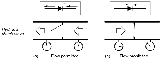
Adding a forward biased diode to every switch in a matrix prevents harmful shorts. For a design where one row is driven high and all other rows are driven low, closing two switches in a single column can directly connect the row driven high with a row driven low in a switch matrix only comprising of switches. However, if a normally forward biased diode is placed in series with both of these closed switches, only the diode connected to the row driven high would be forward biased. The diode connected to the row driven low would be reversed biased preventing the harmful short.

Using diodes on every switch is costly. Most computer keyboard do not use this approach. Instead they use clever circuitry and layouts to prevent shorts and improve their perceived performance. In reality, almost all computer keyboard have an n-key-roll-over limit. A point at which the keyboard fails to detect or distinguish a new pressed key while other keys are already pressed.

For a graphic example of the behavior of a forward and reversed biased diode consider this image from allaboutcircuits.com where the diode on the left is in forward biased and the diode on the right is in reversed bias:

enter image description here

0

Mega has 70 inputs, 86 if you use a '2560 in a full breakout board. I offer a couple of form factors to access all pins at http://www.crossroadsfencing.com/BobuinoRev17

Chess board will always have multiple pieces in multiple rows and multiple columsns pressed until near the end of the game. I'd wire up each square individually, make life a lot easier. Read ports 8 pins at a time, 8 reads to have all 64 squares read.

Your Answer

By clicking “Post Your Answer”, you agree to our terms of service and acknowledge you have read our privacy policy.

Not the answer you're looking for? Browse other questions tagged or ask your own question.