0

The sample code is this:

Sample code for Edgar Bonet

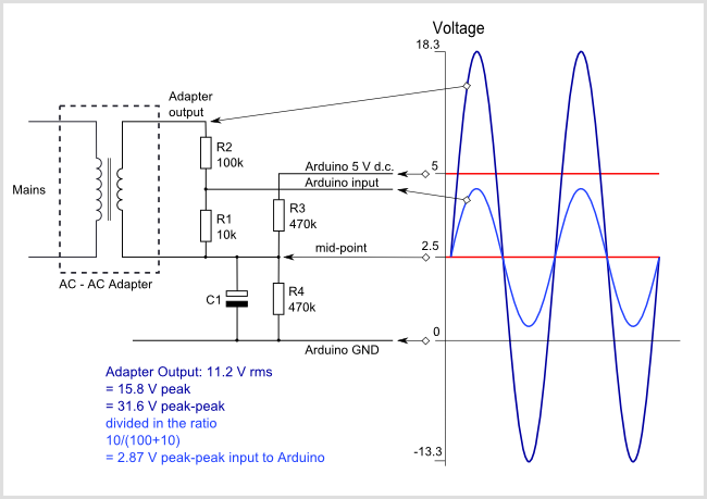
I have questions. I need to integrate the analog sine wave of 60 Hz, this signal described in the next picture, adding an offset near 2.5 V, because I can damage the Arduino board with the negative signal cycle. Internally on the Arduino board, I remove this offset, multiplying by 2, and subtracting 1.

V1=analogRead(A0)*2/1023.0-1.0;

The sampling period must be at least fs=300 Hz, T=1/fs and V1 is the signal I need integrate.

What modifications can I make to Edgar Bonet's code?

Schematic and waveform

5
  • You are new, so consider the critique as constructive in intention. The title is not descriptive. The edit changed the circuit AND the nature of the question AFTER three people answered. One thorough response to the wrong question was deleted by its author. There is a conversion formula with the wrong denominator adjacent to text stating the translation to voltage is not needed. The purpose of integration is unclear without reading an IEEE document. Code indentation does not aid readability. Multiplication by 2 is unexplained. The correspondence between the block and the schematic is unclear. Commented Jun 28, 2017 at 8:28
  • you probably want to understand the essence of your goal vs. your approach. cosine modulation is a fancy way of saying that you control the firing angle non-linearly so the (power) output is linear - as linear control of phase angle will yield a non-linear output.
    – dannyf
    Commented Jun 28, 2017 at 9:52
  • once you understand that you will come to a couple points: 1) you don't need to adc to get it to work; 2) you don't need to integrate to get it to work;
    – dannyf
    Commented Jun 28, 2017 at 9:53
  • if you really want to go down this path, consider the use of of a hardware integrator;
    – dannyf
    Commented Jun 28, 2017 at 9:54
  • if you have to do it with software, consider the use of a differential adc. that can be done via a mcu with a different adc, a hardware solution, or use two single-ended adc channels and calculate the difference. For example consider adc the opamp's output as well.
    – dannyf
    Commented Jun 28, 2017 at 9:55

3 Answers 3

1

V1=analogRead(A0)*2/1023.0-1.0;

This will give you the voltage across R1 in units of 2.5 V. I do not know whether you care or not about the units but, if you want the voltage in volts, then:

  • the voltage at the Arduino input is analogRead(A0) * (5.0/1024)
  • to get the voltage across R1, you have to subtract 2.5 V
  • to get the voltage at the output of the transformer, you have to multiply by 11.

This could be written as

float V = (analogRead(A0) * (5.0/1024) - 2.5) * 11;

but, in order to minimize the number of floating point operations, you can simplify it to

float V = analogRead(A0) * (55.0/1024) - 27.5;

You could then integrate the voltage by running it through a function like this:

static float integral(float x)
{
    static float y;                         // last filter output
    static uint32_t last_sample;            // last time sampled
    uint32_t now = micros();
    float dt = (now - last_sample) * 1e-6;  // step time in seconds
    last_sample = now;
    y += x * dt;
    return y;
}

Now, there is an issue with this approach: the average voltage at the input of the Arduino is not going to be exactly 2.5 V, because your resistors R3 and R4 will not have identical resistance. Then the output of the integral will slowly drift and eventually become unreasonably large.

One way to mitigate this drift problem is to measure this average using the same Arduino running the same program: disconnect the mains, see how the output of the program drifts, and measure the drift rate. Then you subtract the drift rate from the 27.5 in the code, and fine tune until there is no drift at all. There is, however, the risk that some time later it will drift again, due to components changing behavior as the temperature changes.

A better option would probably be to not integrate, but instead use a first-order low-pass filter. Such a filter behaves like an integrator for any signal faster than its cutoff frequency but, unlike a simple integrator, it has a finite gain at zero frequency. You can turn the integrator into a low-pass filter simply by changing the line y += x * dt; into

y += (x - y/tau) * dt;

where tau is the time constant of the filter.

2
  • 1
    Now I understand why SE experts overlook opportunities to gain a few rep points by gathering more requirements in the question's comments section. I wasted quite a bit of time answering a question that has completely changed, and I'm shell shocked now. Thanks for the discussion however. That was the only thing of interest that came out of my answering in this case. :) Commented Jun 28, 2017 at 8:33
  • Thanks Edgar Bonet, the low pass filter worked very well. I could already integrate the signal. Happy week. Commented Jun 30, 2017 at 23:31
1

Brief Electrical Comment First

The circuit as depicted seems sound, but it may be wise to measure the max and min peaks with an oscilloscope or multi-meter to ensure you are within the voltage range of the Atmel chip on the Mega 2560, which is zero Volts to Vcc [1] per Atmel processor's spec sheet [1].

Since Vcc is 5V per the Mega's schematic [2], the safe range you depicted is correct, however you cannot trust the voltage on the mains to stay within IEEE specifications, the p-p secondary Voltage of the adapter to be dead on in proportional relation to the primary, or the resistors to be in the center of their 5% or 10% range of precision. You may wish to add some potentiometers to your circuit to make adjustments.

Now the Math and Software Implementation

Continue to take the i,t (integer, time) sample vector as in the example you referenced. I changed the variable names to be more descriptive from a systems engineering point of view.

int s_in = analogRead(input_pin);
unsigned long microsecs = micros();

The algebraic (not code) relation of the sample to the instantaneous voltage is as follows.

v_in = 5V X s_in / 1024

v_no_offset = v_in - v_offsreallyreallyet

v_offset = 2.5

v_secondary = v_no_offset X (110 KOhms / 10KOhms)

Keep in mind here that the sample is not a p-p measurement. It is an integer representing a Voltage measurement over a very small time range relative to the period of an approximate [3] 60 Hertz sine wave. There is no reason to multiply samples or corresponding Voltages by two for this circuit.

The period of a 60 Hertz sine wave is 16,667 usec, so the difference between your max value and min value for any given 16,667 usec period's worth of samples is your p-p Voltage for that period. You can average those over time to get a less instantaneous p-p Voltage. Before considering p-p or RMS calculations, you must first computing the secondary Voltage corresponding to the integer sample acquired in the analogRead.

Substitution and calculation in mV instead of Volts yields this.

mv_secondary = (5000 X s_in / 1024 - 2500) X (110000 / 10000)

Translating into C, which will be interpreted correctly within an Ino sketch, and using a simplified expression and long integers to achieve reasonable computational speed and accuracy [4] you get this.

int s_in = analogRead(input_pin);
unsigned long microsecs = micros();
unsigned long mv_secondary = 53711L * s_in / 1000 - 27500;

The v,t (secondary Voltage, time) vector is now in the variables mv_secondary and microsecs respectively. Then calculate the delta time and find the product to sum.

unsigned long nano_volt_second = mv_secondary * u_sec_delta;

System Design Considerations

In designing the system, it is often better to delegate the conversion to physical units and the Gaussian approximation of an integral to another part of the system (as in the case of when the embedded program is doing data acquisition but not control) or not do it at all (as in the case when control is in the same board as the data acquisition and the PID parameters superseded the need to translate the integers from readAnalog to physical units altogether).

To achieve the higher loop speed when using USB transfer of the values, one can USB transfer the return values of the analogRead more directly as two byte pairs and perform calculations on the USB peer computer (workstation or other computing hardware). Conversion of integers of any type to strings slows a data acquisition loop down considerably, and should be avoided.

Hardware triggering of the ADC subsystem of the Atmel chip can also increase speed, especially if the analogRead function is bypassed by a lower level implementation of the register reading. At sampling speeds above 200KHz, completely within the capability of the Arduino Due, every usec counts.

Ambiguous Intent Reference to Integration

The summing of products isn't actually integration, which is a symbolic operation, not a calculation. The example reference given does a Gaussian discrete approximation of an integral. The reason for seeking that approximation is not given.

The result of such a calculation would be the product of the time over which the approximation is made and the offset, which would naturally be zero except for any calibration error and low frequency noise in the secondary winding's circuit.

If the intention is to calculate Voltage RMS, there is another real time methodology for that. If you want the average p-p Voltage, there's another (partly described above) for that. If you want to track spikes on the line, then you probably want a circuit with over-Voltage protection and a different algorithm.

Usefulness of Optimized Math

The use of unsigned long for optimization may not be necessary for low frequency applications [5], but any system that needs to meet the Nyquist criterion for audio will require a sample rate where the fixed point simulation may cause a statistically significant number of delays over the time of sampling.

Even if the speed is not needed, exceeding the Niquest criteria permits gaining extra bits of accuracy if windowing is used during data reduction.

References

[1] Atmel 2560 cpu spec sheet @ http://www.atmel.com/Images/Atmel-2549-8-bit-AVR-Microcontroller-ATmega640-1280-1281-2560-2561_datasheet.pdf

[2] Mega 2560 schematic @ https://www.arduino.cc/en/uploads/Main/arduino-mega2560-schematic.pdf

[3] A Voltage waveform from a power grid is rarely if ever a perfect sine wave.

[4] Arduino use of long integer constants as in C/C++ discussion @ https://www.arduino.cc/en/Reference/IntegerConstants

[5] The maximum Δt before the unsigned long product overflows is given by `floor ((2^32 - 1) / (53,711 x 1023 / 1000 - 27,500)) = 156,485 usec, corresponding to a 6.39 Hz sample rate.

2
  • I timed yous computation of the integral at 49 µs, v.s. 50 µs for my floating point version. Worth the trouble? Your avoidance of floats looks to me like premature optimization. If you do have a performance issue, then fixed-point is definitively a worthwhile optimization technique, but doing it right is trickier than you may think. I would not recommend fixed-point to a newbie, unless it is a requirement or clearly worthwhile for his project. Commented Jun 27, 2017 at 12:25
  • @EdgarBonet, more than worth the trouble ... necessary in many if not most cases. The sample rate of 20KHz is far below the Due's capability. Perhaps the test code is string USB transfers instead of packed byte arrays. Optimization to avoid delays in faster loops is require to meet the Nyquist criterion for full spectrum audio & faster control apps. ... Reducing s/n ratios for weak signals requires multiples of the Nyquist. ... In sampling 60 Hertz, the code above does not require floats, fixed point libraries, or testing overflow . See [5] and the other material added to the answer. Commented Jun 28, 2017 at 8:01
-1

The signal will saturate.

You should increase the attenuation if you want to be able to add the full cycle. Or add half cycle and make assumptions about the other half.

As to the code you simply needs to convert the ADC readings to a DC reading and subtract the center offset from it . Much better to do that in the ADC reading domain. Like this

Y = analogread(AIN) - 2.5 * 1023 / Vref;

1
  • Why would it saturate? The attenuation appears to be excessive, leading to unnecessarily loss of bits of accuracy. ... Also, your formula is incorrect in that you are missing the parentheses around the subtraction. Commented Jun 28, 2017 at 8:13

Your Answer

By clicking “Post Your Answer”, you agree to our terms of service and acknowledge you have read our privacy policy.

Not the answer you're looking for? Browse other questions tagged or ask your own question.