12

TL;DR - Can the six yellow ISP pins be used as a normal ISP?


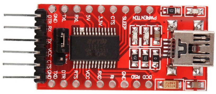
The usual USB-TTL FTDI breakout board looks like this:

USB-TTL FTDI Breakout board

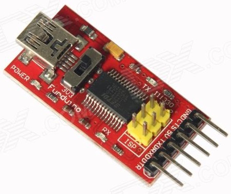
Recently, I came across a variant of the board shown below. However, what are the additional yellow header pins on this board for? They are labelled ISP.

USB-TTL FTDI Breakout board with ISP

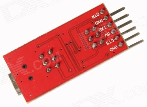
Here is a view of the rear:

USB-TTL FTDI Breakout board with ISP rear

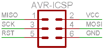
So can they really be used as a standard ISP/ICSP?

AVR-ICSP

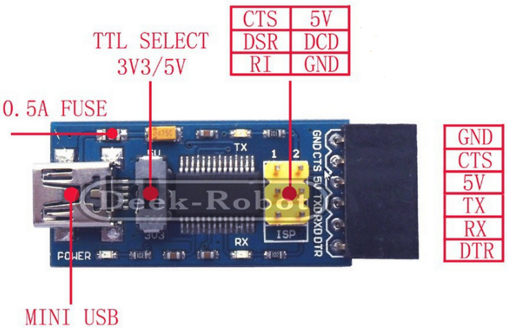
However, according to the diagram below, which labels the 6 pins in question, I am not sure that there is a valid correlation of signal lines.

USB-TTL FTDI Breakout board with ISP with legend

That is to say, would CTS to MISO, RI to RST, DSR to SCK and DCD to MOSI work? Or is that why a special version of avrdude is required, as alluded to in FT232RL: USB to Serial 232 TTL Adapter –?and ISP? - post #6:

As a new feature there is a 6-pin ISP header available. With it, avrdude and avrftdi you can program Atmels and Arduino bootloaders. A special version of avrdude with compiled FTDI driver is neccessary.

However the provided link to that version of avrdude, with the compiled FTDI driver, is dead.

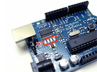
It is also said, in post #7, that these pins are actually equivalent to an X3 connector, as found on the older Arduino Dicimila/NG/Duemilanove boards.

X3 header on Diecimila

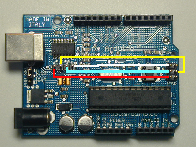
and those can (evidently) be used like so, as a bit banged SPI,

Connecting X3 header to ISP header on Diecimila

It should be noted that the RI, CTS, DCD and DSR (labelled RSD) pins are available, along the sides of the original FTDI breakout board. So, does the breakout board with the ISP header just provide access to these same signals using a different header?

I am a little confused - have I just over thought this, and this breakout board is simply an ISP/ICSP header and an FTDI connector rolled into one board (when used with the appropriate version of avrdude)? Or is it not a usual ISP header? I can not find any specific documentation relating to this type of breakout board, as stated in post #4.

Can anyone say, definitively, what these six pins are for? If they are not a normal ISP header, could you provide a detailed way of using it? A schematic would be helpful.

2
  • I have the same product, did you figure out how to get 3.3V? The output is fixed on 5V and the switch seems to be useless. Commented Jul 27 at 9:58
  • @TeoMaragakis - No sorry, I don't think that I ever tried, and I'm not even sure if I still have it (not used it for a long time). Try checking the switch's solder points (with a DMM) for a bad contact. Try spraying contact cleaner onto (into) the switch. Check the PCB traces to and from the switch for a broken trace (again with a DMM set on continuity mode). Worst case scenario, you could desolder the broken switch and either solder in a replacement switch or put in some header pins to manually link yourself (with a jumper link or jumper cables) Commented Jul 27 at 15:34

2 Answers 2

15

There's a thread about that on the Arduino Forum - someone had a similar question.


I found a schematic (below) which is not for that board, however the header pins are labelled the same as you found, so it is plausibly similar.
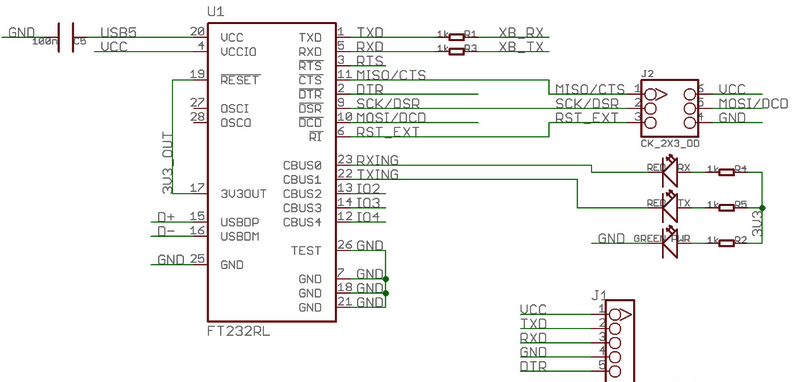
FTDI board schematic

It appears that header is used for "Synchronous Bit Bang mode" as documented here: Bit Bang Modes For The FT232R and FT245R (Application Note AN_232R-01, Document Reference No.: FT_000339)


You can in fact configure that header to be an SPI programmer, as described for example, in FT232R Bitbang Programmer.


I made up a test as I had a similar board in my parts drawer:
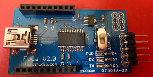
FTDI board front

It had provision for a 6-pin header similar to yours. Turning the board over we can see that they were labelled exactly the same as yours:
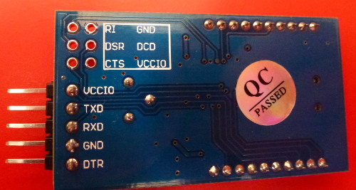
FTDI board back

I soldered on a header (in yellow, to be consistent) giving me this:
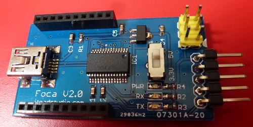
FTDI board with header

I added a white dot to indicate pin 1 (visible on the edge) so I plug the cable in the right way around.


When I attempted to use the board I got this message from avrdude:

avrdude: error: no libftdi or libusb support. Install libftdi1/libusb-1.0 or libftdi/libusb and run configure/make again

So, it had to be compiled from scratch! I am using Ubuntu 14.04 if you are trying to follow along. :)


Download avrdude

Go to the site http://www.nongnu.org/avrdude/

I downloaded version 6.3 source: http://download.savannah.gnu.org/releases/avrdude/avrdude-6.3.tar.gz

Install libusb and libftdi

Before compiling I had to grab libusb and libftdi:

sudo apt-get install libusb-1.0-0-dev
sudo apt-get install libftdi-dev

Compile avrdude

Now we make avrdude after extracting the archive and navigating to its folder:

./configure --enable-libusb --enable-libftdi
make

Find correct configuration

Inside the avrdude.conf file which comes with avrdude I found (after some pondering) this seems to be the correct entry:

# see http://www.geocities.jp/arduino_diecimila/bootloader/index_en.html
# Note: pins are numbered from 1!
programmer
  id    = "arduino-ft232r";
  desc  = "Arduino: FT232R connected to ISP";
  type  = "ftdi_syncbb";
  connection_type = usb;
  miso  = 3;  # CTS X3(1)
  sck   = 5;  # DSR X3(2)
  mosi  = 6;  # DCD X3(3)
  reset = 7;  # RI  X3(4)
;

The mapping of pins to numbers works like this... From the PDF about bit bang mode mentioned above we have this table, with annotations in blue by me:
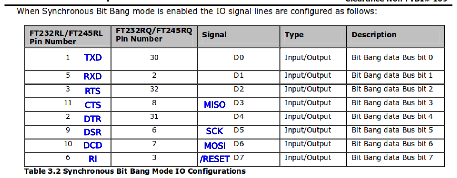
Bit bang mode pins

The numbers refer to the bit number (i.e. in the range 0 to 7) in the "bit banged" data byte. We can see from the earlier schematic that, for example, MISO on the ICSP header is wired to CTS on the FT232RL. Thus MISO is data bit 3, which we tell avrdude in the above configuration. Similarly SCK is data bit 5, and so on.

I attempted to test like this:

./avrdude -C avrdude.conf -carduino-ft232r -pm328p  -v

Fix permissions

I got a permissions error which was fixed by creating a file in the folder /etc/udev/rules.d/ called 71-FTDI.rules. Inside this is:

SUBSYSTEMS=="usb", ATTRS{idVendor}=="0403", ATTRS{idProduct}=="6001", MODE:="0666"

The numbers may vary for your board. You need to find the vendor and product ID. In Ubuntu you can do lsusb and see (amongst other things):

Bus 003 Device 061: ID 0403:6001 Future Technology Devices International, Ltd FT232 Serial (UART) IC
                       ^^^^ ^^^^

Note the two hex numbers, which get copied into the rules file.

After doing that, tell the system to reload the rules:

sudo udevadm control --reload-rules

Then unplug and replug the FTDI board to get it to notice the new permissions.

Test board detection

Finally, the avrdude line above works and reads the chip:

avrdude: AVR device initialized and ready to accept instructions

Reading | ################################################## | 100% 0.01s

avrdude: Device signature = 0x1e950f (probably m328p)
avrdude: safemode: hfuse reads as DE
avrdude: safemode: efuse reads as FD

avrdude: safemode: hfuse reads as DE
avrdude: safemode: efuse reads as FD
avrdude: safemode: Fuses OK (E:FD, H:DE, L:FF)

avrdude done.  Thank you.

I had mine plugged into an ATmega328P.


Example connected to a Diavolino

Programming an Atmega328P

Once we have got this far you just connect the FTDI board to your target board with a straight-through cable.


Summary

The FTDI board you have (and the one I have) can be used as a ICSP programmer for the AVR chips, as described above. Thus a simple board can be both a USB to serial converter, and also an ICSP programmer.

I see similar boards selling on eBay for around $5 so that is probably quite a cheap programming option.

6
  • Thanks Nick. Yes, that thread on the Arduino forums is the one that I referenced in my question, but it wasn't really clear as to how to use it - but it usefully pointed to the X3 header blog. The second link you provide seems to expand upon that topic even further, excellent, thanks. However, there still isn't any blog specifically written for this particular board, which is odd. Commented Oct 27, 2016 at 0:30
  • I believe that if you do this, you would be talking to the FTDI as a USB device and no longer using the operating system's serial port API, so there may be additional setup/driver/permission issues depending on what system one is using to host it. FTDI's more capable FT4232H/FT2232H/FT232H parts are often used this way as JTAG interfaces to more advanced processors. Commented Oct 27, 2016 at 0:44
  • 3
    See amended answer. I got my board to work as an ICSP programmer.
    – Nick Gammon
    Commented Oct 27, 2016 at 4:16
  • 1
    Fantastic, great work. That is the documentation that I was after. Commented Oct 27, 2016 at 8:24
  • would it be possible to repeat the experiment in windows? I find it a very interesting topic Commented Aug 24, 2020 at 8:31
1

Arduino IDE:

Additional programmers.txt entries to use "FT232R as ISP"

ftdi232rasisp.name=FT232R as ISP
ftdi232rasisp.communication=usb
ftdi232rasisp.protocol=arduino-ft232r
ftdi232rasisp.program.tool=avrdude
ftdi232rasisp.program.extra_params=

avrdude.exe with FTDI bitbang support https://github.com/mariusgreuel/avrdude

Your Answer

By clicking “Post Your Answer”, you agree to our terms of service and acknowledge you have read our privacy policy.

Not the answer you're looking for? Browse other questions tagged or ask your own question.