3

I'm doing a little project that requires a lot of sensors. Right now I'm using 4, but i want to reach up to 60 sensors, and a minimum of 16 (for me that's a lot). So, I have an Arduino MEGA 2560, and I'm new to Arduino (Had a little experience with PIC before).

I've started my project with buttons and leds to simulate the sensor, but my sensors work normally HIGH, and when something pass in front of it, it goes quickly to LOW and back. English is not my first language so I don't recall the name of this sensor, kind of like movement sensor(?).

A lot of stuff pass normally, up to 50/s, in front of it, so it should keep "bouncing" between HIGH and LOW. But when I changed the buttons for the sensors, sometimes my processor won't react, and I think it's because the signal goes back to HIGH before the code reads it. Maybe it's not a problem when it's sensing lot of things, but I can't test it right now with a lot of sensors, and it's not something that can keep getting errors.

So I got to interrupts, reading the awesome gammon review. I understood a lot of new things that i didn't know and I searched for a interrupt Library, but the one I found can't use too many sensors.

I forgot to tell, but I'm using a touch 2,4" shield too, so a lot of interrupts pins can't be used.

Will I be able to use all the sensors I want? If not, could I do it with 2 Arduinos and 1 screen? Am i missing something about the interrupts? Where can I find something to help me?

Edit 1: All the sensor are the same

2
  • 1
    What you want here are pin change interrupts
    – Majenko
    Commented Aug 30, 2016 at 20:47
  • This actually would be a great candidate for implementing on a CPLD with lots of pins.
    – Majenko
    Commented Aug 30, 2016 at 22:18

3 Answers 3

6

On a Uno, all of the digital and analog pins can trigger a pin-change interrupt. That gives you 20 inputs straight away. The Mega also has pin change interrupts but not on all its pins. The pins that the Mega supports for pin-change interrupts are documented on the Software Serial page.

Not all pins on the Arduino Mega and Arduino Mega 2560 support change interrupts, so only the following can be used for RX: 10, 11, 12, 13, 14, 15, 50, 51, 52, 53, A8 (62), A9 (63), A10 (64), A11 (65), A12 (66), A13 (67), A14 (68), A15 (69).

(Note that the Atmega2560 chip itself supports more pin change interrupts, however those extra ones are not brought out to header pins on the Arduino board).

That's still quite a few (18 if I counted correctly). Plus the hardware interrupt pins: 2, 3, 18, 19, 20, 21.

Right now I'm using 4, but i want to reach up to 60 sensors, and a minimum of 16

To reach 60 you probably want an input shift register such as the 74HC165 - you can daisy-chain them together to get lots of inputs. However you would have to poll to see if pins changed.

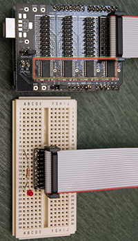
Otherwise you could use something like the MCP23017 chip, which has 16 input/output pins, and supports interrupts. You can use 4 of them (interfacing with I2C) and thus get 64 inputs. There is a shield that has 4 of those chips on it:

Centipede board

With suitable software (see my page about I2C) you could configure for interrupts and read any of those 64 inputs when they change.


Do I have to keep checking all the time for every sensor one by one?

No, because you can configure the interrupts as open-drain, which means you can connect them all together (if you want to). Or, you could bring out the interrupts for the 4 x MCP23017 chips to four interrupt inputs on the Mega (that narrows down for you which chip caused the interrupt). Then you can read the chip's register(s) to find the state of the pins - either at the time of the interrupt, or right now.

However you might find that it is actually faster to just poll the chips (say) 100 times a second. There is some overhead to using I2C, you can also get SPI versions of that chip (MCP23S17) which would operate a bit faster.

Alternatively, the 74HC165, whilst simpler, could also turn out to be overall faster if you just poll rapidly.


And the sensor sense a lot of movement per second, won't that cause trouble for the Arduino?

You need to define "a lot" and "trouble". You won't do billions of read a second. You can probably do thousands. What would you do with thousands of readings anyway? The time taken to process them would probably be the limiting factor.


At the same time I'm using a GPS, no problem for the usage of Serial and I2C together right?

No problem, because serial input is interrupt-driven. Within reason, you can do both at once.

3
  • That quote, “Not all pins on the Mega and Mega 2560 support change interrupts”, is slightly misleading as an explanation of only 18 PCI pins on the Mega. ATmega640-1280-1281-2560-2561 series chips support 24 PCI pins – #0-#7 on PB0-PB7; #8-#15 on PE0 & PJ0-PJ6; #16-#23 on PK0-PK7. However, PE6 and PJ2-PJ6 aren't brought out to headers, leaving 18 available as you mention. Commented Aug 31, 2016 at 5:48
  • The OP said I have an Arduino MEGA 2560 so I was addressing the Arduino board, not the raw processor. I'll amend the post to make that clearer.
    – Nick Gammon
    Commented Aug 31, 2016 at 5:57
  • So, I read about the Centipede Shield and your page about I2C and now I'm pretty sure I need to use I2C one way or another. I'm thinking about the Centipede, but I'm not sure I understood how to implement it. Do I have to keep checking all the time for every sensor one by one? Or one time for each Chip? My master will only read, it's all sensors anyway. And the sensor sense a lot of movement per second, won't that cause trouble for the Arduino? At the same time I'm using a GPS, no problem for the usage of Serial and I2C together right (newbie question)?
    – Kolarovic
    Commented Aug 31, 2016 at 14:26
3

For that many sensors (way more than the number of interrupts available on the chip), your interrupt service routine (ISR) will need to be able to poll the sensors to discover which one(s) caused the interrupt.

That might mean connecting each motion-sensor's output to both a latch and a many-input OR-gate to one of the interrupt pins. Your ISR would have to read the latches; set a flag for each LOW latch; clear the latches (to HIGH) and exit. The main routine would then take whatever action was needed for each sensor that had been LOW.

1

When you have implemented the solution given above, by Nick Gammon, it is recommendable that you try both of the solutions he provides, and use the timer circuit to time each version of the algorithm.

That is: You need to try out if the polled reading he mentions of lets say 100 times per second, or the interrupted method is the best, given your circumstances.

Reason being that if your system pulls the interrupts from time to time, lets say, each of the 64 inputs pulls its interrupt pin maybe once in 30 seconds, then you have just above 2 pulls per second to the board. That is not a lot, and checking the registers like 100 times per second (if you need time wise accuracy for instance), may prove very time consuming, as you would otherwise only run 2 interrupted algorithms per second.

Use the diode on the Arduino Mega circuit board if you have no display or output unit on the Arduino, to display the results. (If you need help communicating from the Arduino to yourself (human) via 1 diode, such that you can be told how much different a particular setup is, then let me know - that would be outside of the scope of this answer, I guess). I short, you can communicate to yourself by creating a little algorithm which starts with ie. 3 rapid blinks, then a pause, then it can create countable blinks for each figure, counting 0 with 10 blinks, and then you can count the blinks by putting breaks in between the figures. Thereby you can communicate the figure 1874 by 1 blink, pause, 8 blinks, pause, 7 blinks, pause, 4 blinks - then long pause, then 3 short blinks, pause, then it repeats.

Your Answer

By clicking “Post Your Answer”, you agree to our terms of service and acknowledge you have read our privacy policy.

Not the answer you're looking for? Browse other questions tagged or ask your own question.