0

I'm trying to get 110dB out of a 25khz Piezo Transducer. This piezo resonates at 25khz and as per the illustration in its datasheet should emit 110dB with 10 volts and 25khz frequency.

Any assistence as to what I'm doing wrong here would be GREATLY appreciated !!

My code is bit-banging it. With an oscilloscope, I confirmed that I'm getting a nice clean 25khz square wave.

I have attached a step-up circuit to the device and am seeing 10volts across the terminals of the piezo while it is emitting it's 25khz frequency.

However, instead of 110dB, I'm only getting 50dB.

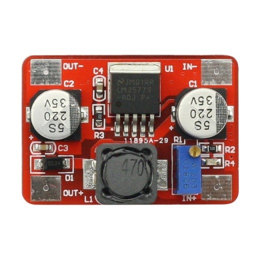
I've tried upping the voltage to 20, and still get the same volume level. The voltage is adjustable via the screw on the top of the blue capacitor on the Voltage Step Up (pictured below).

I've tried changing the duty cycle having HIGH go for 25microseconds and LOW go for 5microseconds. I've tried several combinations and a 50/50 duty cycle appears to achieve maximum volume which is 50dB.

Here's how I'm connected: 1. The inputs of the Step Up are attached to GND and 3.3V pins on the Arduino. 2. The output+ of the Step Up is connected to 1 pin of the Piezo. 3. The output- of the Step Up is NOT connected to anything. (tried to connect it to GND but it didn't change anything. 3. The other pin on the Piezo is connected to D11 on the Arduino.

I'm Running the following code:

 #include<Wire.h>

const int SPK = 11;

void setup()
{
  Serial.begin(9600);
  pinMode(SPK, OUTPUT);
  digitalWrite(SPK, LOW);
}

void loop()
{
  long startTime = millis();
  for (int i = 0; i < 25000; i++)
  {
    digitalWrite(SPK, HIGH);
    delayMicroseconds(15);
    digitalWrite(SPK, LOW);
    delayMicroseconds(15);
  }

  Serial.println(millis() - startTime);
}

Voltage Step-Up Module

UPDATE:

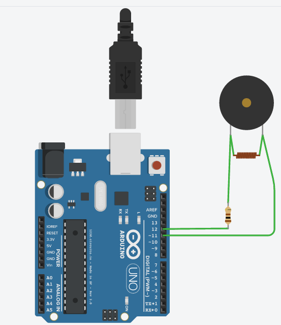
Ok, I am now set up to look like this: enter image description here
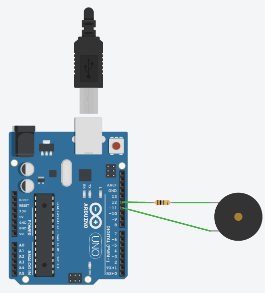
Is this the next step (ie: Adding an Inducer) ?

enter image description here

1
  • How have you mounted the piezo? Just like speakers, it's all about the enclosure. Also, solidly mounting it to something, means any deflection of the piezo means movements of air, instead of movement of the piezo if it's just hanging in free air.
    – Gerben
    Commented Jun 14, 2016 at 13:38

2 Answers 2

1

The device you pictured seems to be a switch-mode power module which will output 10V DC. Get rid of it before you do any damage.

You don't post any link to data, but I assume you mean the Transducer needs 10V peak-to-peak.

This can easily be accomplished by using 2 digital outputs, connected to the transducer, and driven in anti-phase.

The answer to Push-Pull tone code may be an answer to your problem, but may be overkill. If you just want to output a single tone it is easily done with simple code.

I don't know why you think the transducer outputs 50dB. If it really is doubling the drive voltage will only give 56dB.

6
  • Ye HAAA!!! We're getting closer.. I'm at 85dB now at 1" away from the piezo. Any ideas how to get 25 more db out of the piezo?? It may not need a full 10 volts to achieve 110db. We're really close, but I need 110db. Any ideas how to achieve this?
    – Curtis
    Commented Jun 14, 2016 at 7:31
  • @Milliways, isn't your anti-phase comment more like 2.5 volts peak-to-peak for a 5 volt Arduino? That is, if you put an AC coupled scope across the transducer ... I think you would see it deflect up 2.5 volts then down 2.5 volts.
    – st2000
    Commented Jun 14, 2016 at 12:50
  • @st2000 the same misinterpretation was made in a comment to my original linked question. The answer I made then still applies. It is simple circuit theory.
    – Milliways
    Commented Jun 14, 2016 at 12:53
  • @Milliways, I'm here to learn, so tell me why you are right. The linked question was about an inductive load. Guessing, a piezo may appear as a capacitive load? Is that why you are saying it will retain a potential for a total of 5v + 5v = 10v after the switch? If so would adding a (tuned) capacitor-resistor-circuit in series add to this effect?
    – st2000
    Commented Jun 14, 2016 at 13:42
  • @st2000 I am quite willing to help, although this would be better asked as a question on the EE site. Unfortunately I can't give a lesson in circuit theory in comments. Marenko's comment is correct, but it has nothing to do with inductive or capacitative loads. My original Q was about piezo (which is capacitative) - in fact the push-pull is better, because it puts no nett DC across the transducer. You just have to work out the instantaneous voltages at either end then TRANSFORM to a common reference. Why not give it a try - it works, and is common method- previously used in power amplifiers.
    – Milliways
    Commented Jun 14, 2016 at 23:59
1

Alternatively there are COTS parts (Common Off The Shelf) which are simpler to use and may satisfy your requirements. This is just the 1st one I found (search for "5 volt piezo buzzer"). Of course you have no control over the frequency. These type of devices are just to get your attention (you didn't say what your application was for). While it works at 5 volts it is only rated at 85dB @ 10cm. It appears to contain an internal driver so (apparently) only needs 3 to 15 volts to start making noise. It is specified to draw 10mA at 12V. So be careful and measure the current (using a power supply, not from an Arduino) demand at 5 volts. I think the GPIO pins on an Arduino can only handle less than 40mA. So stay well below that to be safe.

Your Answer

By clicking “Post Your Answer”, you agree to our terms of service and acknowledge you have read our privacy policy.

Not the answer you're looking for? Browse other questions tagged or ask your own question.