2

In my house, I have a low voltage AC signal (0-10V) that is proportional to the amount of current that is drawn at any moment (or as it is presented: kW) (europe, 50Hz). Presently, it is just shown as a dial in my kitchen, of course I would to log this. I want to rectify and integrate this singnal over an appropriate time span (maybe on minute) As far as I can see, I basically have two ways of doing this:

  1. The pure arduino approach: Using a voltage divider to get it down to 0-5 V (after rectification) (and maybe throw in a zener diode as an extra protection) Then using an adc in the arduino and measure the voltage directly. The problem I foresee with this approach is that I will need a pretty high sampling rate to make sure I get the peak values. If I managed to sample at exactly the same frequency as my mains,I could just calibrate the measured value (unless I managed to hit the cross overs) but I do not think that would be feasible So I think I need to maybe sample on approx 500 Hz and pick out the highest value from each 1/50 second.

  2. Using an opamp, a few resistors and a capasitor to set up an analog integration circuit, then use the arduino to read out and reset that at appropriate times. Setting up the integration circuit is no problem for me, but I need some feedback on the reset circuit. I have been looking around a bit, but I have not found any standard way to reset an integrator circuit, it seems like the idea is that it should be integrating for as long as it is running.. As far as I can see, as long as it running on <= 5V, I could use an input on the arduino to drain it? - I would then need to make the dimensions such that the low current the arduino input draws will allow the integrator to be reset fast enough.

Any comments? Have I overlooked something? is there a third approach that I have not been thinking about? Is the 1st approach easier that what I think?

4
  • proportional to the amount of current that is drawn at any moment (or as it is presented: kW)” Is it current or wattage you are reading? They are not the same: If you have inductive loads in your house (motors...) or switched-mode power supplies, and want to estimate the consumed power, you will have to monitor the mains instantaneous voltage (at least the phase) and multiply current × voltage. Simply multiplying RMS(current) by RMS(voltage) works only with resistive loads. Commented Mar 3, 2016 at 15:02
  • What I have is a voltage, what the meter tells me it knows is the "wattage"- I don't know if it is true kW or to which degree it is messed up with inductive load (althoug at least at wintertime, most of my usage is for heating, which should be pretty resistive load) Commented Mar 3, 2016 at 15:27
  • 1
    If that voltage is an image of the wattage, you should just run a low-pass filter on it, with no prior rectification. Commented Mar 3, 2016 at 15:32
  • Thanks works like a charm! typical what (watt?) happens when you know a bit of a topic but do not really know it - and ends up with a too complicated solution... Commented Mar 4, 2016 at 21:58

3 Answers 3

3

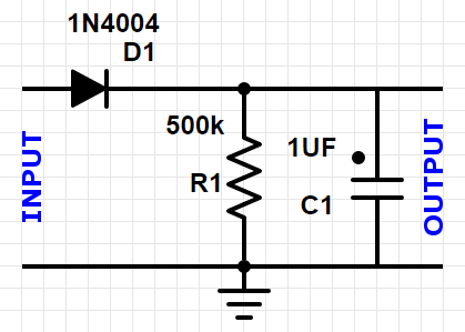
Sorry, but.. Why integration? Just use a peak detector like this one:

enter image description here

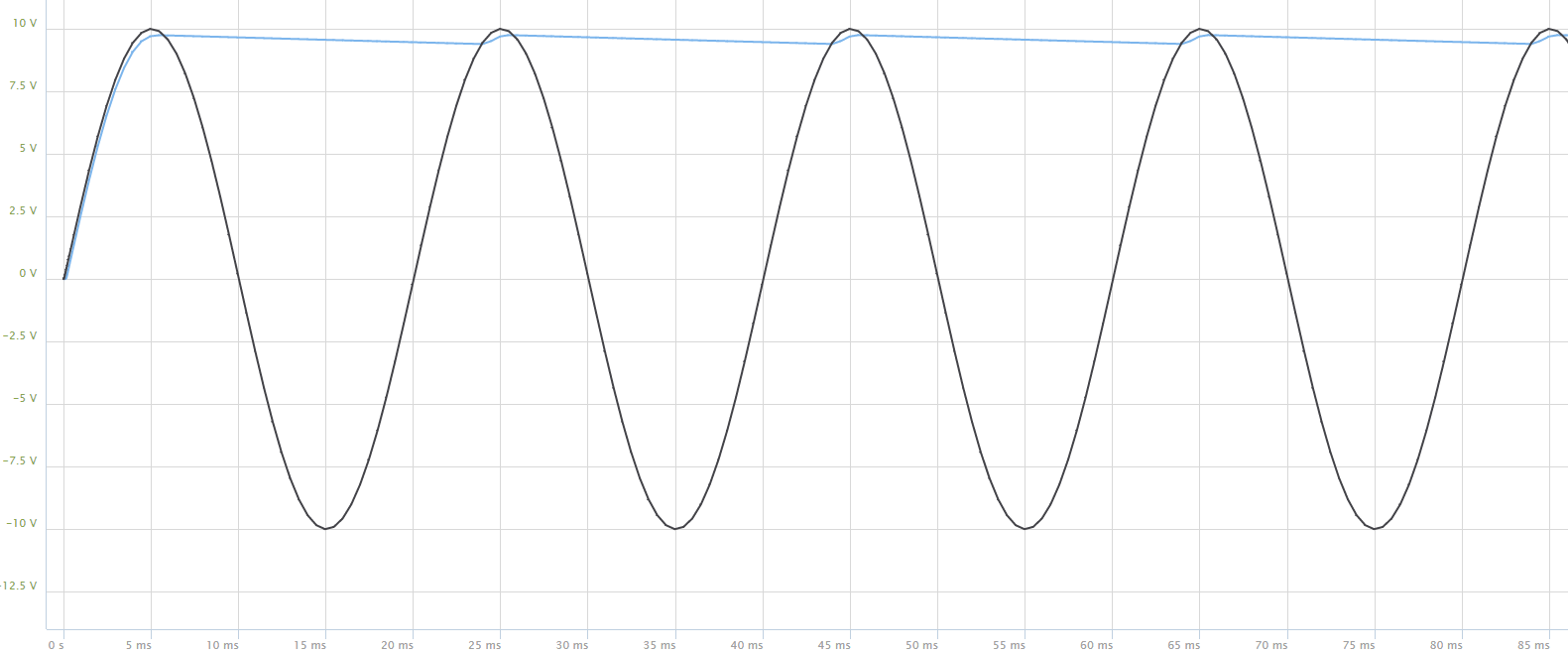
The output will "float" to the peak value of the input signal, minus the voltage drop across the diode:

enter image description here

The output oscillates between 9.7V and 9.2V, which is a 5% maximum error. If you want to reduce it, sample with a sample rate not multiple of 50Hz and average the measures.

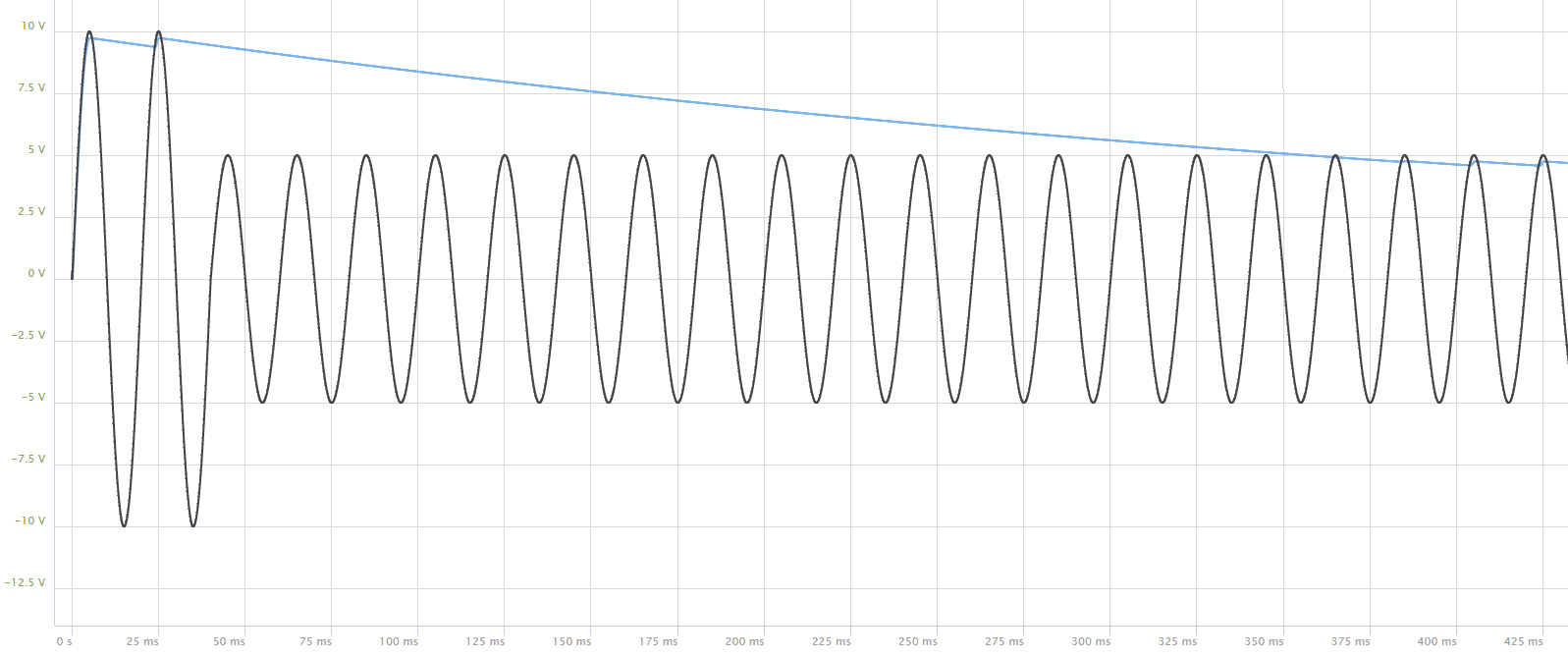
The RC constant is 500ms. This means that it will require less than a second to pass from a value to a lower one:

enter image description here

Here in almost 500ms it will go from 10V to 5V.

If you want to reduce the diode effect (9.7V instead of 10V) use a schottky diode. This, however, will not reduce the 9.2V effect.

You should divide by 2 the voltage; you can either

  1. divide it before the diode (but then the diode effect will be more evident - you can however correct it in software
  2. divide it after the circuit (In this case, replace the 500k resistor with two 250k resistors and take the voltage in the middle)

Of course 500k and 250k are not standard values, but you can use any nearby value without affecting the behavior

3
  • That's pretty cool - that was the third option I didn't think about Commented Mar 3, 2016 at 15:08
  • 1
    Again thanks, I have implemented it, works like a charm! Commented Mar 4, 2016 at 21:01
  • Glad it worked :)
    – frarugi87
    Commented Mar 5, 2016 at 12:28
1

With an Arduino Uno, you can get 9615 samples per second from an analog input, and do the data processing at the same time. That's more than enough to reliably detect a peak. For this, you have to set the ADC to "free running mode" and do the processing in the ADC interrupt service routine. Se this answer for a detailed explanation and code.

Oh, and instead of peak detection, you could just integrate your signal. That should be simpler, and simple is good for interrupt-driven data processing.

0

I'm not quite clear on the 'peak' detection - this would mean your reading would be changing several times a second potentially. Does the current in your house vary that much per second? I don't think your electricity meter is that clever anyway (there must be a smoothing effect, I reckon). For example, if you turned on your electric kettle for 1/50th of a second, would your domestic meter accurately record that (or the 0-10V signal vary)? I personally doubt it but I'm no meter designer! Anyway, you also mention that you want to log over a minute? I'm unclear on the exact requirements here.

Anyway, if you are reading the 'max' current (so you can accurately calculate bills, for example) I think your first approach would work - after all a 50Hz sampling rate is very low for an Arduino. You won't need a 500Hz sample rate as the data doesn't change that frequently anyway, does it?

Perhaps you could trigger the sampling activity by synchronising to the mains frequency (which you sort of allude to) and then do the reading? Use an analog input to detect the rising LV mains cycle and then do the reading? Or use a Schmidt trigger to trigger the Arduino (sounds a bit of overkill, I think the Arduino could do it all).

Experimentation is called for to see what works and what doesn't but your first approach seems eminently feasible to me.

1
  • I must have been a bit unclear, when I was talking about peak detection, I meant to measure (close to) the sinus peak to avoid aliasing effects. Commented Mar 3, 2016 at 15:11

Your Answer

By clicking “Post Your Answer”, you agree to our terms of service and acknowledge you have read our privacy policy.

Not the answer you're looking for? Browse other questions tagged or ask your own question.