2

I want to trigger an arduino from a sound from an audio jack from a mobile phone. The audio is a 1 Khz sound that the mobile will play. I want to avoid accidental triggering of the audio by testing for specifically that frequency.

I've found several tutorials using analog read, but the output is not in hertz.

How do i get the output in Hertz?

int incomingAudio;

void setup(){
    Serial.begin(9600);  
}

void loop(){
  incomingAudio = analogRead(A0);//read voltage at A0
  incomingAudio = (incomingAudio+1)/4 - 1;//scale from 10 bit (0-1023) to 8 bit (0-255)
  if (incomingAudio<0){//deal with negative numbers
    incomingAudio = 0;
  }
  PORTD = incomingAudio;
  Serial.println(PORTD);

}
2
  • Edgar Bonets Program is ingeneous, but the power fluctuations tested with a tone at 1000 kHz (square wave Signal) are quite high. A factor of three using LOG_TAU = 6. May be, some improvement is possible. Commented May 12, 2018 at 13:34
  • @ChristianRempel: Testing with synthetic data shows the reported power fluctuates within a factor 2.2 with a square input and a factor 1.2 with a sinusoidal input. Commented May 13, 2018 at 15:46

2 Answers 2

6

You can measure a single "pure" frequency by counting the number of times that the pin changes, by using the inbuilt timers. Here is a sketch from my page about timers that accomplishes that:

// Timer and Counter example
// Author: Nick Gammon
// Date: 17th January 2012

// Input: Pin D5

// these are checked for in the main program
volatile unsigned long timerCounts;
volatile boolean counterReady;

// internal to counting routine
unsigned long overflowCount;
unsigned int timerTicks;
unsigned int timerPeriod;

void startCounting (unsigned int ms) 
  {
  counterReady = false;         // time not up yet
  timerPeriod = ms;             // how many 1 ms counts to do
  timerTicks = 0;               // reset interrupt counter
  overflowCount = 0;            // no overflows yet

  // reset Timer 1 and Timer 2
  TCCR1A = 0;             
  TCCR1B = 0;              
  TCCR2A = 0;
  TCCR2B = 0;

  // Timer 1 - counts events on pin D5
  TIMSK1 = bit (TOIE1);   // interrupt on Timer 1 overflow

  // Timer 2 - gives us our 1 ms counting interval
  // 16 MHz clock (62.5 ns per tick) - prescaled by 128
  //  counter increments every 8 µs. 
  // So we count 125 of them, giving exactly 1000 µs (1 ms)
  TCCR2A = bit (WGM21) ;   // CTC mode
  OCR2A  = 124;            // count up to 125  (zero relative!!!!)

  // Timer 2 - interrupt on match (ie. every 1 ms)
  TIMSK2 = bit (OCIE2A);   // enable Timer2 Interrupt

  TCNT1 = 0;      // Both counters to zero
  TCNT2 = 0;     

  // Reset prescalers
  GTCCR = bit (PSRASY);        // reset prescaler now
  // start Timer 2
  TCCR2B =  bit (CS20) | bit (CS22) ;  // prescaler of 128
  // start Timer 1
  // External clock source on T1 pin (D5). Clock on rising edge.
  TCCR1B =  bit (CS10) | bit (CS11) | bit (CS12);
  }  // end of startCounting

ISR (TIMER1_OVF_vect)
  {
  ++overflowCount;               // count number of Counter1 overflows  
  }  // end of TIMER1_OVF_vect


//******************************************************************
//  Timer2 Interrupt Service is invoked by hardware Timer 2 every 1 ms = 1000 Hz
//  16Mhz / 128 / 125 = 1000 Hz

ISR (TIMER2_COMPA_vect) 
  {
  // grab counter value before it changes any more
  unsigned int timer1CounterValue;
  timer1CounterValue = TCNT1;  // see datasheet, page 117 (accessing 16-bit registers)
  unsigned long overflowCopy = overflowCount;

  // see if we have reached timing period
  if (++timerTicks < timerPeriod) 
    return;  // not yet

  // if just missed an overflow
  if ((TIFR1 & bit (TOV1)) && timer1CounterValue < 256)
    overflowCopy++;

  // end of gate time, measurement ready

  TCCR1A = 0;    // stop timer 1
  TCCR1B = 0;    

  TCCR2A = 0;    // stop timer 2
  TCCR2B = 0;    

  TIMSK1 = 0;    // disable Timer1 Interrupt
  TIMSK2 = 0;    // disable Timer2 Interrupt

  // calculate total count
  timerCounts = (overflowCopy << 16) + timer1CounterValue;  // each overflow is 65536 more
  counterReady = true;              // set global flag for end count period
  }  // end of TIMER2_COMPA_vect

void setup () 
  {
  Serial.begin(115200);       
  Serial.println("Frequency Counter");
  } // end of setup

void loop () 
  {
  // stop Timer 0 interrupts from throwing the count out
  byte oldTCCR0A = TCCR0A;
  byte oldTCCR0B = TCCR0B;
  TCCR0A = 0;    // stop timer 0
  TCCR0B = 0;    

  startCounting (500);  // how many ms to count for

  while (!counterReady) 
     { }  // loop until count over

  // adjust counts by counting interval to give frequency in Hz
  float frq = (timerCounts *  1000.0) / timerPeriod;

  Serial.print ("Frequency: ");
  Serial.print ((unsigned long) frq);
  Serial.println (" Hz.");

  // restart timer 0
  TCCR0A = oldTCCR0A;
  TCCR0B = oldTCCR0B;

  // let serial stuff finish
  delay(200);
  }   // end of loop

Feeding in a 1 kHz sine wave (from 0V to 5V) I get this output:

Frequency Counter
Frequency: 1000 Hz.
Frequency: 1002 Hz.
Frequency: 1000 Hz.
Frequency: 1000 Hz.
Frequency: 1000 Hz.
Frequency: 1000 Hz.
Frequency: 1002 Hz.
Frequency: 1000 Hz.
Frequency: 1000 Hz.
Frequency: 1000 Hz.

There is the occasional mis-reading but it looks accurate enough. You might sample a few times, and if you get something between 990 and 1010, five times, you might consider that a match.

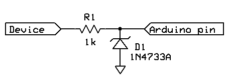
You will need to make sure that the input is in the range for triggering the input circuitry of the Arduino. It should be around 4 to 5V, and not higher than 5V (for a high). It also should not go negative.

Something like this will protect the input pin:

Input protection

Warning - audio from an audio jack will be AC and it will go negative. Make sure you use a suitable input protection.


Amplification

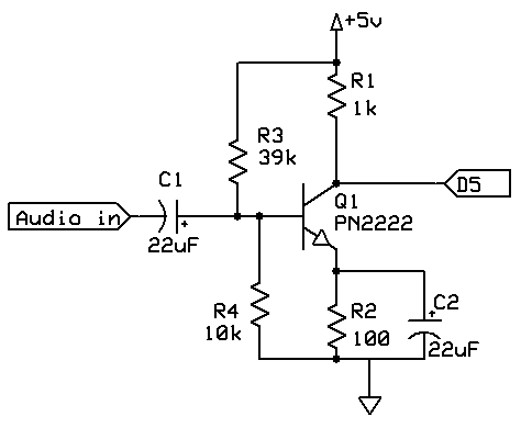
After looking at Wikipedia - Line level it seems likely that the output from your phone will not be high enough (around 700 mV probably). Therefore a simple transistor amplifier will probably be required to raise it to a level that can be detected.

Inspired by this post on Electronics Stack Exchange, I made up a simple amplifier:

Audio amplifier schematic

Testing out with around 500mV peak-to-peak input indicates that it successfully amplified it to 0 to 5V DC:

Audio amplifier scope trace


Alternative method with analog comparator

Based on suggestions by Chris Stratton, there is another way of doing this.

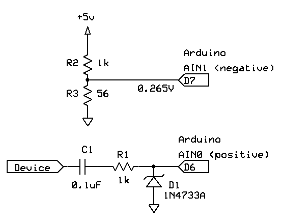
You can use the analog comparator to detect an analog signal passing a threshold, like this:

Analog comparator schematic

I have set up the voltage divider to trigger at 0.265V, so that a 500 mV signal should provide an acceptable triggering range.

As for the sketch, at these frequencies we can do something simpler than what I posted before:

volatile bool counting;
volatile unsigned long count;

ISR (ANALOG_COMP_vect)
  {
  if (counting)
    count++;
  }

void setup ()
  {
  Serial.begin (115200);
  Serial.println ("Started.");
  ADCSRB = 0;           // (Disable) ACME: Analog Comparator Multiplexer Enable
  ACSR =  bit (ACI)     // (Clear) Analog Comparator Interrupt Flag
        | bit (ACIE)    // Analog Comparator Interrupt Enable
        | bit (ACIS1);  // ACIS1, ACIS0: Analog Comparator Interrupt Mode Select (trigger on falling edge)
   }  // end of setup

unsigned long startTime;

void loop ()
  {

  if (!counting)
    {
    startTime = micros ();
    count = 0;
    counting = true;
    }
  else
    {
    // is a second up? (1000000 microseconds)
    if (micros () - startTime >= 1000000)
      {
      counting = false;
      Serial.print (count);
      Serial.println (F(" Hz."));
      }  // end of a second being up

    }  // end of if

  }  // end of loop
7
  • You don't need an amplifier, if you are going to do single-tresholding detection anyway, the ATmega has an analog comparator usable by the timer. What you did miss is the DC blocking capacitor in your first circuit. Choose one that makes the impedance high (especially in combination with any resistor) enough to use the internal protection diodes, rather than trying to find an external one that creates the right limitation. Commented Feb 28, 2016 at 0:00
  • @ChrisStratton : Yes, good idea. I've edited with an alternative method along the lines of what you suggested.
    – Nick Gammon
    Commented Feb 28, 2016 at 0:42
  • I'm afraid you still don't quite have it. The diode remains a distraction and you need to bias to your threshold, which would ordinarily be placed somewhere more like half the operating voltage. Commented Feb 28, 2016 at 1:49
  • Well, @ChrisStratton, I would be pleased if you would post an answer explaining your solution in detail. Just saying that I have it wrong isn't helping me or anyone else, like the OP.
    – Nick Gammon
    Commented Feb 28, 2016 at 1:54
  • you need to bias to your threshold - I was assuming that the incoming signal was around 700mV (Line Level) - and indeed that worked in my test. Feel free to post other figures.
    – Nick Gammon
    Commented Feb 28, 2016 at 1:57
5

If your signal is a pure 1 kHz tone, then you should use Nick Gammon's counting method, as it is the most straight-forward solution. If, however, you are picking the signal through a microphone, chances are you will also get some background noise, and this can make the counting method unreliable.

In such a case, you will have to use some kind of digital filter to extract the desired signal from the noise. I would recommend using homodyne detection, which is both simple and very robust against wide-spectrum noise: let f = 1 kHz be the frequency you want to detect, and t be the current time, then

  • compute cos(2 π f t ) and sin(2 π f t ): these two periodic signals, in quadrature to one another, are called “the local oscillator”
  • multiply your signal independently by the above cos() and sin()
  • low-pass filter the two products, which gives you the I and Q demodulated signals
  • compute the instantaneous power = I2 + Q2.

You know the phone is ringing when this power goes above some experimentally-determined threshold.

I know all this sounds like heavy math, but it need not be:

  • All the computations are amenable to efficient fixed-point implementations, and you can do the math in parallel with the analog-to-digital conversion.
  • The scheme works even with crude approximations of the sin() and cos() functions. Even square waves (sin() and cos() being always +1 or −1) work quite decently.
  • The low-pass filter can be implemented as an exponential moving average, which is only a bit shift, an add and a subtract.

I can try to write some sample code, but I would go through the trouble only if there is interest. If your signal is so clean that Nick Gammon's method works reliably, there probably is no point.


EDIT: I wrote a program to demonstrate this approach, just for the fun. It's available as a GitHub gist: homodyne.ino. I am not copying the whole program here, just adding some explanations:

The first thing is to take care of the sampling frequency. Whenever one wants to do signal processing, it is very desirable to sample at a fixed and known frequency. This is next to impossible to achieve by looping over analogRead(), because the CPU time needed to go through the loop is hard to predict, as it can be influenced by interrupts and by conditional branches. analogRead() is also highly inefficient, as it locks the CPU in a busy loop while it waits for the analog-to-digital converter (ADC) to do its job.

The solution is to put the ADC in the so called "free running mode". In this mode, it starts a conversion as soon as the previous one is finished, which gives a very steady sampling rate of 9.615 kHz (one sample every 104 µs). The samples are handled by an interrupt service routine called ISR(ADC_vect) which gets triggered every time a sample is ready. This is also where all the signal processing is done.

Below is a detailed explanation of every line of code in the ISR:

int8_t sample = ADCH - 128;

Reading the ADC result is the first thing to do in the ISR. Since we do not need the full 10 bit resolution, the ADC was configured to left-adjust its result. Then we get an 8-bit result by just reading the high byte of the ADC data register. We subtract 128 to remove the DC offset and get a signed number in the range [−128 .. +127].

Next, we update the phase of our local oscillator:

static uint16_t phase;
phase += PHASE_INC;

We need not worry about possible overflows: since the phase is kept in units of 1/216 cycles, the increment automatically works modulo one cycle. The phase increment should theoretically be 6815.744, which is rounded to 6816. This makes the local oscillator fast by 0.0376 Hz, which is negligible given the accuracy of the Arduino clock. The phase could be kept in an 8-bit variable, but the rounding error would then make the oscillator fast by 14 Hz, which can be borderline unacceptable.

Next we need to build two square waves in quadrature, which will be used as rough approximations of sin() and cos(). But since the most significant bit of the phase is on during half of the cycle, it can be used as one of our square waves. The other wave is obtained in a similar way, after adding 1/4 cycle to the phase. So here is how we multiply our sample by the square waves:

int8_t x = sample;
if (((phase>>8) + 0x00) & 0x80) x = -1 - x;
int8_t y = sample;
if (((phase>>8) + 0x40) & 0x80) y = -1 - y;

The expression phase>>8 is only meant to hint the compiler that it needs only to consider the most significant byte of the phase. This should normally not be needed, but I noticed that, without this hint, gcc generates suboptimal code. The -1 in the above lines are for avoiding a possible overflow.

Next comes the low-pass filter:

signal_I += x - (signal_I >> LOG_TAU);
signal_Q += y - (signal_Q >> LOG_TAU);

Where signal_I and signal_Q are volatile int16_t globals, and LOG_TAU is 6. This filters with a time constant

τ = 64 × 104 µs = 6.656 ms

which translates to a −3 dB bandwidth of

Δf = 1/(2πτ) = 23.9 Hz.

which is fairly narrow for a 1 kHz signal. The significance of τ is that, once the tone starts, it takes the filter about 2.3 τ ≈ 15 ms to reach 90% of its final output. Both τ and Δf can be changed by simply changing LOG_TAU.

This ISR takes about 176 CPU cycles (11 µs, including the 4 cycles needed to put the CPU in interrupt mode) every 1664 cycles (104 µs). This amounts to about 10.6% of the available CPU power. And since everything is done inside the ISR, the program is free to do whatever else needs to be done while the data acquisition and digital filtering happens in the background.

I tested the program by sending it a sine wave of 4.36 V peak-to-peak amplitude. The reported power fluctuated quite a bit, but here are the approximate average readings as a function of the input frequency:

frequency  |  power
-----------+-------
   929 Hz  |   480
   976 Hz  |  2400
  1005 Hz  |  4600
  1028 Hz  |  2700
  1079 Hz  |   480

Your Answer

By clicking “Post Your Answer”, you agree to our terms of service and acknowledge you have read our privacy policy.

Not the answer you're looking for? Browse other questions tagged or ask your own question.